When buyers ask me about connector pin count, the question is almost always the same: how many pins do I actually need? It sounds simple. In practice, the answer depends on the cable, the circuit, the termination method, and how the system is wired — and getting it wrong means the connector does not fit the job.
2-pin and multi-pin waterproof connectors differ in five key ways: the number of circuits they carry, their physical size and housing design, their current and voltage capacity per pin, the complexity of the mating and locking process, and the range of applications each type serves. Understanding these differences helps you specify the right connector before the cable is cut and the order is placed.
Choosing between a 2-pin and a multi-pin connector is not just about counting wires. Each pin count decision affects the housing size, the sealing design, the assembly process, and the long-term reliability of the installation. Get it right at the specification stage and everything downstream is easier — the sourcing, the installation, and the maintenance.
So I put together this breakdown of all 5 key differences. Whether you are a distributor building a product range or a project manager specifying connectors for an outdoor system, this guide will help you match the right pin count to the right job, understand where each type falls short, and avoid the most common selection mistakes buyers make when pin count is involved.
In the sections below, I will cover circuit capacity, housing size, current rating per pin, mating complexity, and application fit. By the end, you will have a clear framework for making the right pin count decision on any project.
What Does Pin Count Mean and How Do You Decide How Many Pins You Need?
Before comparing 2-pin and multi-pin connectors, it helps to understand what pin count actually means — and how the number of pins in a connector is determined in the first place.
The pin count of a waterproof connector matches the number of wires in the cable it connects. Each pin carries one wire. A 2-core cable needs a 2-pin connector. A 3-core cable needs a 3-pin connector. A 5-core cable needs a 5-pin connector. The cable determines the connector — not the other way around. Choosing a connector with the wrong pin count means the cable cannot be fully terminated.
The number of cores in a cable is determined by the electrical functions the system needs to perform. A simple outdoor light needs two wires — live and neutral. Add an earth wire and you need three. Add a dimming control signal and you need four. Each additional function adds a core to the cable and a pin to the connector.
How is cable core count determined?
| Electrical Function | Cores Required | Connector Pin Count |
|---|---|---|
| Single-phase power, no earth | 2 cores (L + N) | 2-pin |
| Single-phase power with earth | 3 cores (L + N + E) | 3-pin |
| Single-phase power + 1 signal | 4 cores | 4-pin |
| Single-phase power + 2 signals | 5 cores | 5-pin |
| Three-phase power, no earth | 4 cores (L1 + L2 + L3 + N) | 4-pin |
| Three-phase power with earth | 5 cores (L1 + L2 + L3 + N + E) | 5-pin |
| Multi-sensor or data system | 6–12 cores | 6 to 12-pin |
How Are Wires Terminated Inside a Waterproof Connector?
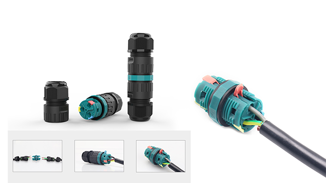
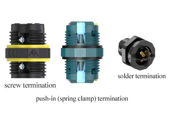
Once you know how many pins you need, the next question is how the wires connect to the pins inside the connector. There are three main termination methods — and each one affects installation speed, reliability, and the tools required on site.
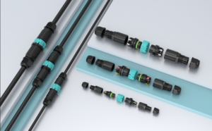
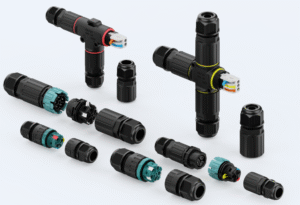
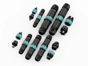
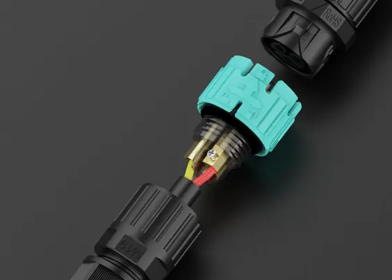
Waterproof connectors are available in three termination methods: screw termination, push-in (spring clamp) termination, and solder termination. Each method determines how the wire is secured inside the connector housing — and that choice affects installation speed, the tools required on site, whether the connection can be re-opened, and which pin counts are available in each format.
Leading connector manufacturers like Wieland and Phoenix Contact have built entire outdoor connector systems around the push-in termination method — precisely because it eliminates tools, reduces installation errors, and cuts wiring time by up to 80% compared to screw termination. Phoenix Contact’s IPD installation system uses push-in technology with a bayonet fast-locking system, allowing tool-free installation even in difficult-to-access locations, with IP68 protection throughout. Wieland’s RST series offers 2 to 7-pin waterproof connectors with both screw and spring connecting technology, rated up to 600V and 53A, with mechanical coding that prevents installation errors.
Screw, push-in, and solder termination compared
| Factor | Screw Termination | Push-In Termination | Solder Termination |
|---|---|---|---|
| Tool required | Screwdriver | None | Soldering iron |
| Wire preparation | Strip only | Strip only (ferrule for fine stranded) | Strip + tin |
| Installation time per wire | 60–90 seconds | 10–15 seconds | 2–4 minutes |
| Re-terminable | Yes | Yes — lever release | No — permanent |
| Vibration resistance | Good with correct torque | Good | Excellent |
| Conductor cross-section | 0.5–6 mm² | 0.5–2.5 mm² | 0.5–2.5 mm² |
| Pin count range (AGX) | 2–6 core | 2–5 core | 2–24 core (LP series) |
| Best use case | Heavy outdoor power, high current | Fast field installation, frequent access | Permanent high-reliability assembly |
Wire identification markings on AGX connectors
Every AGX screw and push-in connector has wire identification markings printed directly on the housing body next to each terminal port. This follows the same convention used by Phoenix Contact’s QPD system, where wire guides are marked 1, 2, 3 and so on, so installers can centre conductors automatically without referring to a wiring diagram. On AGX products the marking system works as follows:
| Core Count | Marking Type | Labels Used |
|---|---|---|
| 2-core | Letter | L, N |
| 3-core | Letter + symbol | L, N, ⏚ |
| 4-core | Number | 1, 2, 3, 4 |
| 5-core | Number | 1, 2, 3, 4, 5 |
| 6-core (screw only) | Number | 1, 2, 3, 4, 5, 6 |
For 2-core and 3-core connectors, the letter and symbol system maps directly to the standard outdoor wiring convention — L for live, N for neutral, and the earth symbol for protective earth. For 4-core and above, numbered labels give the installer a clear, unambiguous reference for every wire position without requiring a printed wiring diagram on site. This reduces connection errors, particularly on multi-core installations where one misplaced wire can affect the entire circuit.
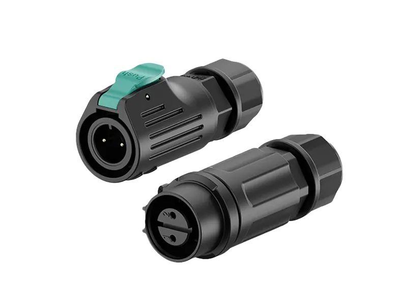
What Is the LP Series Male-Female Waterproof Connector and When Do You Use It?
Screw and push-in connectors handle wire-to-wire and wire-to-panel connections well. For applications where two devices or cable assemblies need to mate and unmate repeatedly — sensors, equipment, portable devices — a dedicated male-female connector pair is the right solution. That is what the LP series is designed for.
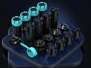
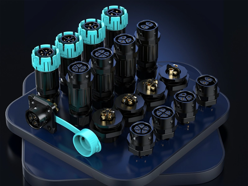
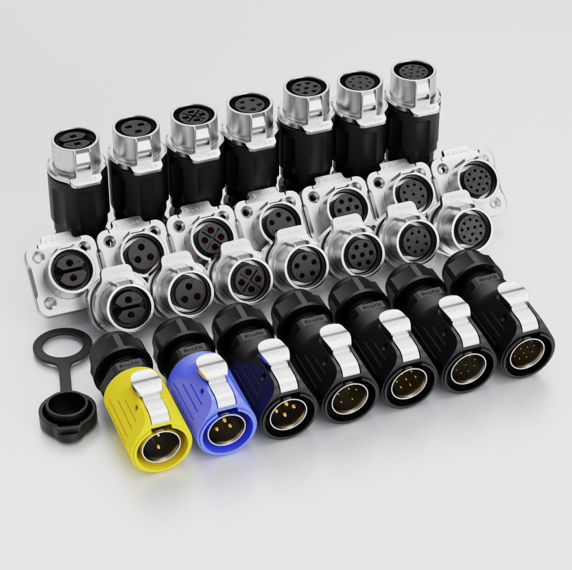
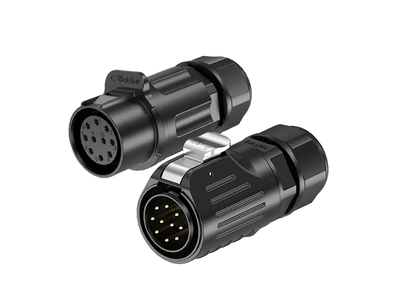
The LP series is a circular male-female waterproof connector available in 2-core to 24-core versions, rated IP68. The male and female halves mate together and lock with a threaded ring. Every LP connector includes a keyed housing — a physical anti-mismating design that prevents the male half from inserting in the wrong orientation. This keying protects the pins from bending and prevents cross-connection between different circuits.
The anti-mismating design is not just a convenience feature. On a multi-pin connector with 8, 12, or 24 pins, inserting the male half one position off will bend multiple pins simultaneously. Bent pins mean the connector cannot be used — and in most cases, the housing must be replaced. The keyed design on the LP series eliminates this risk entirely. The male half can only insert in one orientation, which means it either mates correctly or it does not mate at all.
LP series connector range
| Pin Count | Typical Application | Circuit Type |
|---|---|---|
| 2-pin | Simple power connection | Single-phase L + N |
| 3-pin | Outdoor power with earth | L + N + earth |
| 4-pin | Power + signal device | Power + control signal |
| 5-pin | Three-phase + earth | L1 + L2 + L3 + N + earth |
| 8-pin | Multi-function sensor | Power + multiple data signals |
| 12-pin | Complex equipment interface | Mixed power and signal |
| 16-pin | Industrial machine connection | Multi-axis or multi-function |
| 24-pin | High-density device interface | Maximum circuit consolidation |
When does the LP series fit better than screw or push-in connectors?
| Condition | Screw or Push-In | LP Series Male-Female |
|---|---|---|
| Connection is permanent | ✅ Best choice | Possible but over-engineered |
| Connection is mated and unmated regularly | ❌ Not designed for this | ✅ Best choice |
| High pin count (8 pins and above) | Limited availability | ✅ Available up to 24 pins |
| Risk of incorrect mating | Moderate | ✅ Anti-mismating keying built in |
| Equipment with a defined connector interface | Not typical | ✅ Standard male-female format |
| Field-replaceable cable assembly | Difficult | ✅ Easy — unmate and replace |
The LP series covers the widest pin count range of any AGX connector family — from the simplest 2-pin power connection to a 24-pin high-density interface. For distributors, stocking the LP series means being able to cover any customer request from a simple garden light connection to a complex industrial sensor interface with a single product family.
Difference 1: How Many Circuits Does Each Connector Actually Carry?
This sounds like the obvious difference — and it is. But the implications go further than most buyers think.
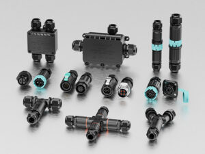
A 2-pin waterproof connector carries exactly two circuits: typically one positive and one negative. Every wire in the system needs its own dedicated connector. A multi-pin connector carries multiple circuits inside a single housing — from 3 pins up to 12 or more — which means one connector handles power, ground, and signal lines simultaneously. Fewer connectors on a system means fewer potential leak points and fewer failure points.
The circuit count decision shapes the entire wiring architecture of a system. A 2-pin connector forces you to run separate connectors for every function — power and signal go through different connectors, sometimes in different locations. A multi-pin connector consolidates everything into one mating point, which simplifies the installation and reduces the number of sealed joints the system depends on.
How does pin count affect system wiring architecture?
| System Requirement | 2-Pin Approach | Multi-Pin Approach |
|---|---|---|
| Power only (live + neutral) | One 2-pin connector | One 2-pin connector |
| Power + earth | Two 2-pin connectors | One 3-pin connector |
| Power + signal | Two separate connectors | One 4-pin or 5-pin connector |
| Power + multiple signals | Multiple connectors | One multi-pin connector |
| Three-phase power | Three 2-pin connectors | One 4 or 5-pin connector |
| Sensor with power and data | Two connectors minimum | One 4-pin connector |
The math is straightforward. Every additional 2-pin connector you add to a system is another sealed joint that can fail, another locking mechanism that can loosen, and another installation step that takes time. Multi-pin connectors consolidate all of that into one housing — one seal, one lock, one mating action.
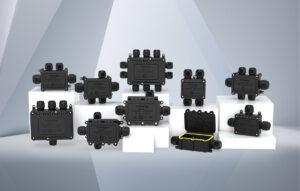
One thing I see often in distributor product ranges: heavy stock of 2-pin connectors but very limited multi-pin options. The buyers who come back most regularly are the ones running complex outdoor systems — smart agriculture, EV infrastructure, street lighting — where 4-pin and 5-pin connectors are the daily workhorse.
Difference 2: How Does Pin Count Affect Housing Size and Sealing Design?
More pins means more contact area inside the housing. That affects the physical size of the connector — and how the waterproof seal is engineered around it.
A 2-pin waterproof connector has a compact housing sized for two contacts and two wire entry points. Multi-pin connectors have progressively larger housings as pin count increases, because each additional pin requires its own contact cavity, its own wire entry seal, and additional space for the locking mechanism to function correctly. A 5-pin connector is typically two to three times the diameter of a 2-pin connector in the same product family.
The sealing design also scales with pin count. A 2-pin connector has two wire entry points to seal — two rubber grommets, two contact cavities. A 5-pin connector has five. Each wire entry must be individually sealed to prevent water tracking along the wire jacket into the connector body. This is why high pin-count connectors require careful wire gauge matching — the grommet size is fixed for a specific wire cross-section range, and a wire that is too thin or too thick will not seal correctly.
How does housing size scale with pin count?
| Pin Count | Typical Outer Diameter | Wire Entry Seals | Relative Connector Size |
|---|---|---|---|
| 2-pin | 15–20 mm | 2 | Compact |
| 3-pin | 18–24 mm | 3 | Small |
| 4-pin | 22–28 mm | 4 | Medium |
| 5-pin | 25–32 mm | 5 | Medium-large |
| 8-pin | 32–40 mm | 8 | Large |
| 12-pin | 40–50 mm | 12 | Very large |
Physical size matters in real installations. In a tight conduit entry, a sensor housing with limited clearance, or a junction box with multiple connectors, the difference between a 20mm and a 32mm connector body can determine whether the design works or needs to be revised. Always check the connector’s outer diameter against the available space before finalizing the specification.
Difference 3: How Does Pin Count Affect Current Rating Per Pin?
This is the most technically misunderstood difference between 2-pin and multi-pin connectors. Most buyers assume more pins means more current capacity. The reality is the opposite.
In a 2-pin waterproof connector, the housing is designed around two large contacts with generous spacing. Each pin can carry a higher current — typically 10A to 30A per pin depending on the model. In a multi-pin connector, contacts are packed more closely together inside a smaller cavity per pin. Heat from adjacent pins accumulates, which reduces the safe current rating per pin — often to 3A to 10A per pin for high pin-count versions.
This is the specification detail that causes the most field failures in connector selection. A buyer sees a 5-pin connector rated at “10A” and assumes all five pins can carry 10A simultaneously. In most designs, that 10A rating applies to a single pin in isolation. When all five pins carry current at the same time, thermal accumulation inside the housing reduces the safe per-pin rating — sometimes significantly.
Current rating comparison by pin count
| Connector Type | Typical Per-Pin Rating (Single Pin) | Typical Per-Pin Rating (All Pins Loaded) | Best For |
|---|---|---|---|
| 2-pin | 20–30A | 20–30A | High-current power runs |
| 3-pin | 15–20A | 12–16A | Standard outdoor power with earth |
| 4-pin | 10–15A | 8–12A | Power and signal combined |
| 5-pin | 8–12A | 6–10A | Three-phase or mixed power/signal |
| 8-pin | 4–8A | 3–6A | Multi-signal, low-current sensor |
| 12-pin | 2–4A | 1.5–3A | Data and control signal only |
Always check the connector’s datasheet for the derating table — the current reduction factor when multiple pins are loaded simultaneously. A reputable manufacturer will publish this. If the datasheet does not include a derating table, ask for it before specifying the connector for any power application.
Difference 4: How Does Mating Complexity Change With Pin Count?
A 2-pin connector mates in one motion. A 12-pin connector requires precise alignment of 12 contacts before the locking mechanism can engage. That difference has real consequences in the field.
A 2-pin waterproof connector is simple to mate because there are only two contacts to align. The connector can often be mated by feel in low-light or confined conditions. Multi-pin connectors require all pins to align simultaneously before the housing seats correctly. Misalignment of even one pin prevents full seating, which means the seal is not fully engaged and the IP68 rating does not apply.
Keying is the engineering solution to this problem. Most multi-pin connectors use a keyed housing — a physical asymmetry in the connector body that prevents the male and female halves from mating at the wrong angle or in the wrong orientation. Without keying, a 5-pin connector could be inserted one position off, bending pins and creating a misconnection that may not be immediately visible.
How does mating difficulty scale with pin count?
| Factor | 2-Pin | 3–4 Pin | 5–8 Pin | 9–12 Pin |
|---|---|---|---|---|
| Alignment difficulty | Very easy | Easy | Moderate | Requires care |
| Keying requirement | Optional | Recommended | Essential | Essential |
| Mating by feel in dark | Easy | Possible | Difficult | Not recommended |
| Risk of bent pins | Very low | Low | Moderate | Higher |
| Time to mate correctly | 5–10 seconds | 10–15 seconds | 15–25 seconds | 20–30 seconds |
| Locking confirmation | Easy to feel | Easy to feel | Check visually | Check visually |
For outdoor installations where connectors are mated in the field — sometimes at height, sometimes in poor weather — mating difficulty is a real operational consideration. For fixed equipment where connectors are mated once in a controlled environment, it matters much less. Match the pin count to the installation conditions, not just the circuit requirements.
Difference 5: Which Applications Call for 2-Pin and Which Need Multi-Pin?
The five differences above all lead to this: which connector fits which job. Pin count is not just a circuit count — it is a system design decision.
2-pin waterproof connectors are best for simple single-circuit power runs where high current is needed and the system has no signal lines to consolidate. Multi-pin connectors are best for systems where power and signal share the same cable run, where reducing the number of connection points matters, or where a device needs multiple electrical functions through one sealed interface.
After 15 years of working with buyers across irrigation, outdoor lighting, marine, and industrial automation, the pattern I see is consistent. Simple power runs — garden lights, single-phase pumps, basic outdoor equipment — use 2-pin and 3-pin connectors almost exclusively. Complex systems — smart sensors, multi-axis equipment, EV charging infrastructure — move to 4-pin, 5-pin, and higher as soon as the design matures.
Application guide by pin count
| Application | Recommended Pin Count | Reason |
|---|---|---|
| Single LED fixture power | 2-pin | Live and neutral only, high current |
| Outdoor pump or motor | 3-pin | Live, neutral, earth |
| Garden lighting with dimming signal | 4-pin | Power + dimming control signal |
| Smart irrigation sensor | 4-pin | Power + two data signals |
| Three-phase outdoor equipment | 5-pin | Three phases + neutral + earth |
| CCTV camera with power and data | 4–5 pin | Power + video or network signal |
| Marine navigation system | 5–8 pin | Multiple power and signal circuits |
| Industrial servo motor | 8–12 pin | Power, encoder, brake, temperature |
| EV charging point sensor | 4–5 pin | Power + communication signals |
| Agricultural field sensor hub | 5–8 pin | Multiple sensors on one connector |
One buying pattern I see regularly with distributors: they start with 2-pin and 3-pin stock, then find their customers asking for 4-pin and 5-pin as projects get more complex. Building the full range from the start — 2-pin through 5-pin at minimum — prevents those lost sales and positions you as a complete connector source, not just a basic product supplier.
Conclusion
2-pin and multi-pin waterproof connectors serve different jobs. Pin count affects circuit capacity, housing size, current rating per pin, mating complexity, and the range of applications each type can handle. None of these differences shows up in a product photo — they are all in the datasheet and in the design of the system the connector goes into.
Use the application guide in Difference 5 as your starting point on any new project. Match the pin count to the circuit requirement, check the per-pin current rating under full load, and confirm the housing size fits the installation space. Those three checks prevent the most common pin count specification mistakes.
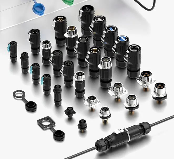
At AGX, we manufacture waterproof connectors from 2-pin through 12-pin across circular, push-in, and assembly formats — all rated IP68. If you are building a product range or specifying connectors for a project, visit agxconnector.com or send us a message. We will help you get the pin count right from the start.