Walk into any electrical supply warehouse in Europe or North America right now and you will notice something. The shelf space for push-in connectors has doubled in the last five years. Screw terminals are still there — but push-in is taking over, one job site at a time.
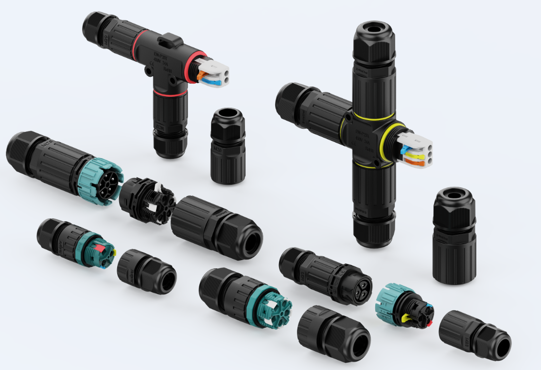
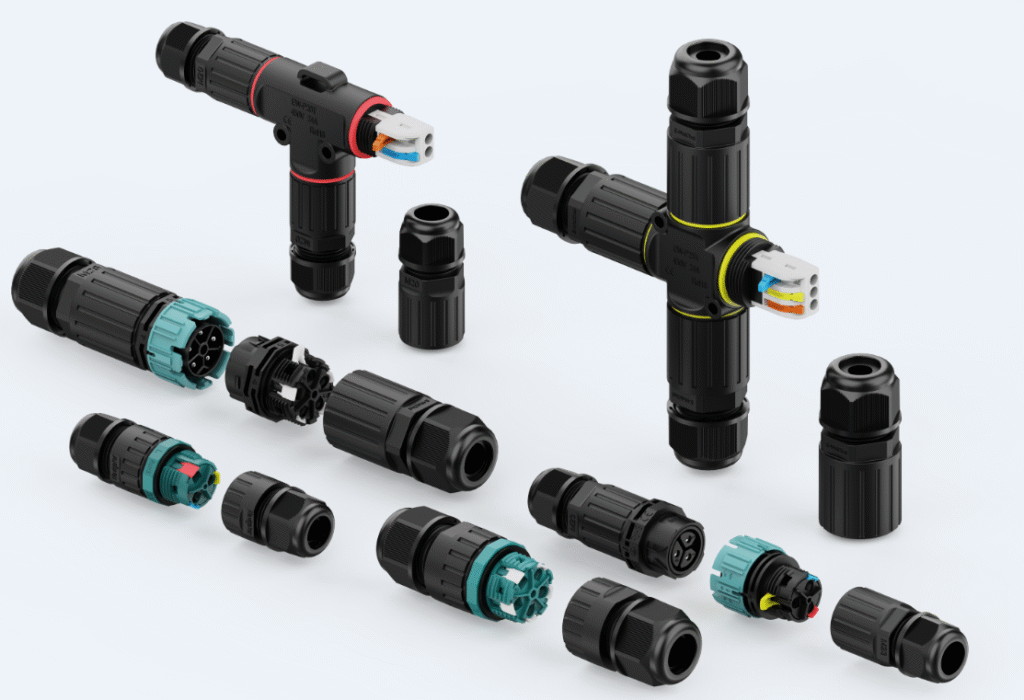
The main categories of waterproof push-in connectors for fast installation are: wire-to-wire connectors (I-type, T-type, and X-type), wire-to-panel connectors (panel-mount and flange-mount), the push-in lever connector, the waterproof push-in butt connector, and the IP68-rated push-in junction connector. Each type serves a different connection task, core count, and installation environment.
The shift to push-in is not about trend. It is about labor cost. A push-in connection takes 10 to 15 seconds. A screw terminal takes 60 to 90 seconds. On a project with 300 connection points, that difference is hours. And hours on a job site cost real money.
So I put together this guide to the five push-in connector types that deliver the most value in real installation conditions. Whether you are a distributor building a product range or a project manager specifying connectors for a large installation, this guide will help you understand which push-in type fits which job, what to check in the spec before you order, and where each type falls short so you are not surprised in the field.
In the sections below, I will walk you through each connector type, how it works, where it performs best, and what to watch out for. By the end, you will know exactly which push-in connector to reach for on your next project.
1. What Are Wire-to-Wire Push-In Connectors and Which Shape Do You Need?
Every outdoor wiring job has two basic connection tasks: join two cable ends in a straight run, or split one cable into two or three directions at a branch point. Wire-to-wire push-in connectors handle both — in three shapes.
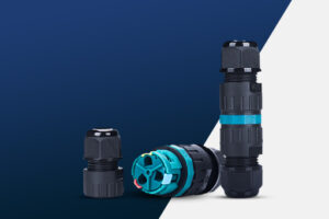
Wire-to-wire push-in connectors come in three body shapes: I-type (straight inline), T-type (three-way branch), and X-type (four-way cross). All three are IP68 rated and use a spring clamp that locks the wire on insertion — no tools needed. I-type is available in 2-core through 5-core. T-type and X-type are available in 2-core and 3-core. Each shape is a sealed standalone unit — no junction box required.
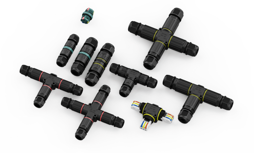
Strip the wire, push it into the port, and the internal spring clamp bites down and holds. The sealed housing closes around every wire entry point and delivers IP68 protection — rated for continuous immersion beyond 1 meter. On a garden lighting run, an irrigation system, or a street lamp installation, these three shapes cover every connection point from the first cable joint to the last branch.
Which shape fits which connection task?
| Shape | Wire Entries | Core Count | Best Use Case |
|---|---|---|---|
| I-type (inline) | 2 — one each end | 2, 3, 4, 5 core | Straight cable extension or mid-run joint |
| T-type (branch) | 3 — T-shaped | 2, 3 core | One feed splitting into two directions |
| X-type (cross) | 4 — all four sides | 2, 3 core | One feed splitting into three directions |
The core count rule is simple: match the connector to the cable exactly. A 3-core cable needs a 3-core connector. A 5-core cable needs a 5-core connector. I-type is the only shape that supports 4-core and 5-core because T-type and X-type are designed for standard outdoor power runs — live, neutral, and earth — where 3-core is the maximum needed.
Core count guide for I-type connectors
| Core Count | Typical Application |
|---|---|
| 2-core | Single-phase power, live and neutral only |
| 3-core | Single-phase with earth, standard outdoor power |
| 4-core | Three-phase without earth, or multi-signal cables |
| 5-core | Three-phase with earth, full industrial power runs |
2. What Are Panel-Mount and Flange-Mount Push-In Connectors Used For?
Wire-to-wire connectors join two cables in open space. But a lot of real installations end at a fixed surface — a control panel, an equipment enclosure, or a wall-mounted housing. That is where panel-mount and flange-mount push-in connectors come in.
Panel-mount and flange-mount push-in connectors are wire-to-panel connectors that fix permanently to a surface on one side, while the other side accepts a push-in wire connection. Both use the same spring clamp mechanism — no tools needed on the wire side. Both are IP68 rated as standalone units. Available in 2-core through 5-core. The difference between them is how they attach to the surface.
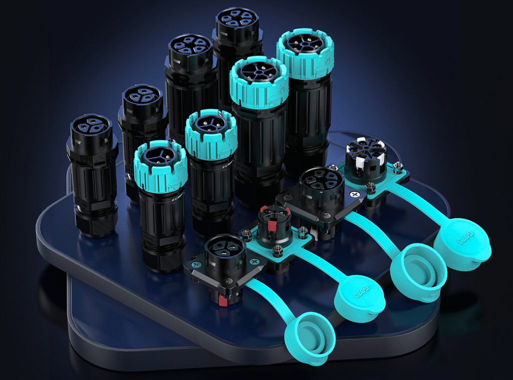
These connectors solve a specific problem: bringing a cable from outside a sealed enclosure to a connection point inside, without drilling a hole and running the wire loose. The connector body passes through a cutout in the panel wall and seals the entry point at IP68. The wire pushes in from outside. The front terminal connects to the internal circuit inside the enclosure. They can also be mounted directly on a waterproof junction box wall — drill the cutout, fit the connector, and the box has a sealed push-in entry point without needing a separate terminal block inside.
Panel-mount vs. flange-mount: what is the difference?
| Feature | Panel-Mount | Flange-Mount |
|---|---|---|
| Mounting method | Passes through panel cutout, locked from behind with a nut | Sits flat on surface, screwed down through flange holes |
| Installation access | Requires access from both sides — nut tightened from the back | Front-only installation — screws go in from the front |
| Panel thickness range | Fixed by thread length — confirm before ordering | Flexible — flange sits flat on any thickness |
| Best surface type | Sheet metal panels, enclosure walls, junction box walls | Thick walls, cast housings, mounting plates |
| IP rating | IP68 | IP68 |
| Core count | 2–5 core | 2–5 core |
| Wire side termination | Push-in spring clamp, no tools | Push-in spring clamp, no tools |
The panel-mount version is the faster of the two to install on thin sheet metal — push the body through the cutout from the front, tighten the locknut from behind, and it is done. The flange-mount version is better on thicker materials where a locknut cannot reach, or when back-panel access is not available.
Where are panel-mount and flange-mount push-in connectors most used?
| Application | Mount Type | Why |
|---|---|---|
| Outdoor lighting control enclosures | Panel-mount | Locknut fixing through thin sheet metal wall |
| Waterproof junction boxes | Panel-mount | Drill cutout on box wall, fit connector, done — no terminal block needed inside |
| Waterproof equipment housings | Flange-mount | Works on thick cast or moulded housings |
| Smart agriculture control boxes | Either | IP68 cable entry point for sensor cables |
| Marine junction enclosures | Flange-mount | Robust fixing on fibreglass or aluminium hulls |
| EV charging infrastructure | Panel-mount | Fast installation on standard metal enclosures |
| Solar combiner boxes | Either | Sealed cable entry, multiple core counts needed |
One thing to confirm before ordering: the cutout diameter for panel-mount types, and the flange hole pattern for flange-mount types. These are fixed by the connector model. Always check the dimensional drawing in the datasheet before cutting or drilling.
3. Why Do Installers Prefer the Push-In Lever Connector for Stranded Wire?
Stranded wire is everywhere in real installations. And stranded wire is exactly where standard push-in connectors start to struggle. The lever connector was built to fix that.
A push-in lever connector uses a flip-down lever to open the spring clamp before wire insertion. You open the lever, insert the stripped wire — solid or stranded — and close the lever to lock it. The lever holds the clamp fully open during insertion, which allows stranded wires to enter cleanly without individual strands bending or missing the contact zone. The connection is re-openable and re-usable.
The lever is a small design change with a big practical impact. Standard push-in connectors rely on the wire itself to deflect the spring during insertion. With stranded wire, individual strands can splay out and miss the contact, creating a partial connection. The lever removes that problem entirely by holding the spring open before the wire goes in.
When does the lever connector outperform standard push-in types?
| Wiring Condition | Standard Push-In | Lever Connector |
|---|---|---|
| Solid core wire | Excellent | Excellent |
| Fine stranded wire (no ferrule) | Poor — strands splay | Excellent — lever holds clamp open |
| Fine stranded wire (with ferrule) | Good | Excellent |
| Frequent re-wiring | Limited — some are single-use | Excellent — fully re-usable |
| Confined spaces | Good — compact | Moderate — lever needs clearance |
| Mixed wire types on same job | Difficult | Easy — handles both |
The lever connector does have one trade-off: it needs more space than a standard push-in connector. The lever has to flip open, which means you need clearance above or beside the connector. In very tight junction boxes, this can be a constraint. Always check the connector dimensions against your box size before specifying.
Key applications for lever connectors
| Application | Reason |
|---|---|
| Smart home and BMS wiring | Stranded signal cables, frequent reconfiguration |
| Modular display and signage | Regular maintenance access needed |
| Outdoor sensor installations | Lever models available in IP68 housing |
| Retrofit and repair work | Re-usable without replacing the connector |
| Mixed solid and stranded wire jobs | One connector type handles both |
4. What Makes a Waterproof Push-In Butt Connector the Right Choice for Outdoor Joints?
Not every connection happens inside a box. Outdoor wire joints — in conduit, under vehicles, in irrigation trenches — need a different solution entirely.
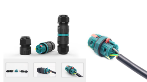
A waterproof push-in butt connector joins two wire ends inline inside a sealed housing that is rated IP68. The push-in spring clamp locks the wire without tools, and the housing is sealed against water, dust, and UV exposure. Some models use a gel-filled interior as a secondary seal. The result is a permanent, weatherproof inline joint that requires no heat gun and no tape.
The waterproof butt connector solves the field wiring problem that every outdoor installer faces: how do you make a quick, clean, weatherproof wire joint without a junction box, a heat gun, or a roll of self-amalgamating tape? The answer is a sealed push-in butt connector. Strip the wire, push in both ends, and the joint is done — sealed and ready for outdoor exposure.
How does a waterproof push-in butt connector compare to other outdoor joint methods?
| Joint Method | Tools Needed | IP Rating | Re-openable | Installation Time |
|---|---|---|---|---|
| Waterproof push-in butt connector | None | IP68 | Some models | 15–20 seconds |
| Heat shrink butt splice | Heat gun | IP68 | No | 60–90 seconds |
| Gel-filled crimp splice | Crimp tool | IP68 | No | 45–60 seconds |
| Screw terminal in weatherproof box | Screwdriver | IP68 (box) | Yes | 3–5 minutes |
| Wire nut with tape | None | Not rated | Yes | 30–45 seconds |
The wire nut with tape is still common on job sites. It should not be used outdoors. Tape ages, cracks, and lets water in. A sealed push-in butt connector costs a little more per unit and takes about the same time. The difference is that the sealed connector still works two years later.
Best applications for waterproof push-in butt connectors
| Application | Notes |
|---|---|
| Outdoor lighting runs | Direct burial or conduit installations |
| Irrigation and agriculture wiring | Soil moisture and chemical exposure |
| Marine and boat wiring | Vibration and saltwater environment |
| Automotive and trailer wiring | Under-vehicle joints, road exposure |
| Solar panel field wiring | UV exposure, rain, temperature cycling |
5. When Is a Push-In Junction Connector with IP68 Rating the Smartest Choice?
For installations where wires meet in an outdoor or wet environment — and where a junction box is too large or too slow — the IP68-rated push-in junction connector is the right tool.
An IP68-rated push-in junction connector combines a multi-port push-in connector block with a fully sealed waterproof housing in a single compact unit. Multiple wires push in from different directions, the spring clamps lock each one, and the sealed housing protects the entire junction against water immersion up to 1 meter for 30 minutes. No box required. No tools required.
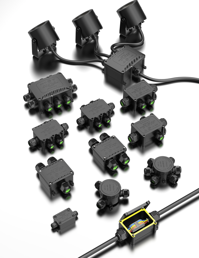
This connector type is still underused in the market, which is a missed opportunity for distributors. The sealed junction connector replaces the combination of a standard junction box, a terminal block, gaskets, and mounting hardware — in a single product that installs in under a minute. For outdoor lighting, irrigation control, and street furniture wiring, this is a significant time and cost saving.
How does an IP68 push-in junction connector compare to a traditional junction box setup?
| Factor | IP68 Push-In Junction Connector | Standard Junction Box + Terminal Block |
|---|---|---|
| Installation time | Under 1 minute | 5–10 minutes |
| Components required | 1 unit | Box, terminal block, gasket, screws, cover |
| IP rating | IP68 built-in | Depends on box and gasket quality |
| Re-openable | Yes | Yes |
| Wire capacity | 3–6 wires typical | Limited by box size and terminal count |
| Size | Very compact | Larger |
| Cost per junction | Moderate | Higher when all components included |
| UV resistance | Check housing material | Check box material |
The one thing to verify with any sealed junction connector is the wire entry seal design. Each wire entry port should have an individual silicone or rubber grommet that seals around the wire jacket. If the wire entry is not individually sealed, the IP68 rating applies only to the housing body — and water can still enter along the wire.
Best applications for IP68 push-in junction connectors
| Application | Notes |
|---|---|
| Outdoor LED street lighting | Compact junction at each lamp post |
| Garden and landscape wiring | Buried or surface-mounted in soil |
| Smart agriculture sensors | Chemical and moisture exposure |
| Outdoor CCTV and security | Compact, weatherproof junction at camera |
| EV charging infrastructure | Outdoor wiring junction between charge points |
Which Waterproof Push-In Connector Shape Do You Actually Need — I, T, or X?
Most buyers think of push-in connectors as a single shape. In practice, the shape of the connector determines how wires can enter and exit — and choosing the wrong shape means adding extra junction boxes or running unnecessary cable.
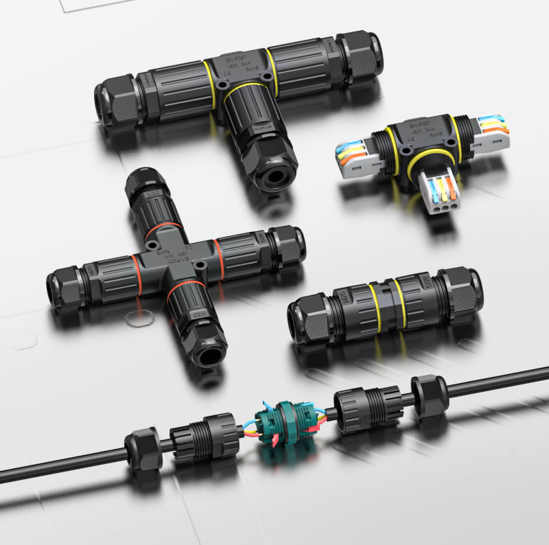
Waterproof push-in connectors come in three body shapes: I-type (straight inline), T-type (three-way branch), and X-type (four-way cross). All three are available with IP68 ratings, meaning they can withstand continuous water immersion beyond 1 meter. Each shape is designed for a different wiring topology, and using the right one eliminates the need for a separate junction box at the connection point.
This is one of the most practical product decisions on an outdoor wiring job. A T-type connector at a branch point takes 20 seconds to install and fits in the palm of your hand. A junction box at the same point takes five minutes and adds bulk to every installation. Over a job with 40 branch points, the difference in labor and materials adds up fast.
How do I-type, T-type, and X-type connectors differ?
| Shape | Wire Entries | Topology | Pin Count Available | Best Use Case |
|---|---|---|---|---|
| I-type (Inline) | 2 — both ends | Straight-through run | 2, 3, 4, 5 cores | Cable extension, point-to-point run |
| T-type (Branch) | 3 — one side entry | One feed, two outputs | 2, 3 cores | Branching from a main cable run |
| X-type (Cross) | 4 — all four sides | One feed, three outputs | 2, 3 cores | Hub point, multi-branch distribution |
The pin count range is worth noting. I-type connectors cover the widest range — 2 cores through 5 cores — because straight inline joints appear in every wiring scenario from single-phase power to multi-core signal cables. T-type and X-type connectors are available in 2-core and 3-core versions, which covers the large majority of outdoor power distribution jobs: live, neutral, and ground.
When should you use each shape?
| Scenario | Right Shape | Why |
|---|---|---|
| Extending a garden lighting cable | I-type | Straight run, two wire ends |
| Powering two lights from one feed cable | T-type | Branch without a box |
| Distributing power to three directions at a crossroads | X-type | Four-way distribution in one unit |
| Connecting 4-core control cable | I-type | Only I-type supports 4 and 5 cores |
| Outdoor string light mid-run branch | T-type | Compact, no box needed |
| Central hub for courtyard or patio lighting | X-type | One point, three outputs |
All three shapes use the same push-in spring clamp mechanism. Strip the wire, push it in, and the clamp locks. The sealed housing closes around the wire entry points and delivers IP68 protection — rated for continuous immersion beyond 1 meter depth. No tape, no heat gun, no junction box required.
Do Male and Female Waterproof Connectors Also Come in Push-In Versions?
Yes — and this is a detail that many distributors miss when building a product range. The push-in termination method is not limited to inline junction connectors. It is also available on the rear wire entry of male and female circular connector halves.
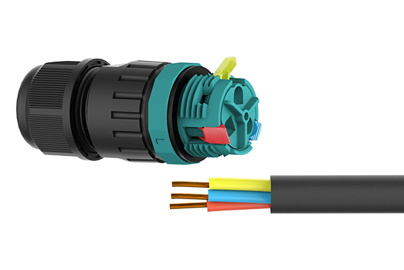
Male and female waterproof connectors with push-in rear termination use the same spring clamp technology as inline push-in connectors, but on the tail end of a standard circular connector housing. The front of the connector still mates with the opposing half in the usual way. The difference is at the back: instead of a screw terminal or crimp, you push the wire in. No tools, no crimping equipment, faster field assembly.
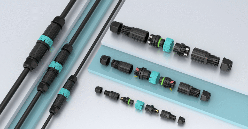
This is a meaningful upgrade for field installation teams. Traditional male and female circular connectors require either a screwdriver for screw terminals or a crimping tool and die set for crimp contacts. Both slow down installation and require trained technicians. The push-in rear termination version requires neither — strip the wire and push it into the back of the connector housing. The spring clamp locks it in place.
How does push-in rear termination compare to screw and crimp on male and female connectors?
| Termination Type | Tool Required | Installation Time | Re-terminable | Skill Level Needed |
|---|---|---|---|---|
| Screw terminal rear entry | Screwdriver | 60–90 sec per wire | Yes | Low to moderate |
| Crimp contact | Crimp tool + correct die | 90–120 sec per wire | No | Moderate to high |
| Push-in rear termination | None | 15–20 sec per wire | Yes (lever release) | Minimal |
The push-in version is compatible with the same IP68 housing designs used on standard circular connectors. The rear wire seal — the individual rubber grommet around each wire entry — works the same way. The only difference is how the wire is secured inside the housing.
Where does the push-in male and female connector make the most sense?
| Application | Why Push-In Rear Termination Helps |
|---|---|
| Outdoor sensor installation | Field wiring without crimp tools |
| Smart agriculture systems | Multiple connection points, no workshop access |
| Temporary event and stage lighting | Fast connection and disconnection |
| Solar field sensor wiring | Remote locations, minimal tooling on site |
| Maintenance and retrofit work | Re-terminable without replacing the connector |
One thing to confirm when ordering: the conductor cross-section range. Push-in rear termination on circular connectors typically handles 0.5 mm² to 2.5 mm², which covers most low-to-medium current sensor and lighting applications. For heavier power cables, screw or crimp termination is still the right choice.
Conclusion
Push-in connectors save time. That is their core value. But the right connector depends on more than just the termination method — it also depends on the shape, the pin count, the IP rating, and whether the application needs an inline junction or a mating connector pair.
This guide has covered the five main push-in connector types, the three IP68-rated body shapes for outdoor wiring, and the push-in termination option for male and female circular connectors. Use it as a reference every time you specify or source push-in connectors for a project.
At AGX, we manufacture the full range — I-type, T-type, and X-type waterproof push-in connectors in IP68, multi-port junction connectors, and male and female connectors with push-in rear termination. If you are building a distributor product range or sourcing for a specific installation, visit agxconnector.com or send us a message. Tell us the application and we will find the right connector for the job.