Most buyers learn connector types by accident — one project at a time, one mistake at a time. After ten years of sourcing, they know the products they have used. They do not always know what they missed.
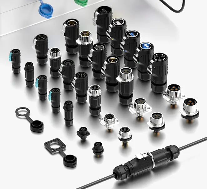
There are 10 common types of electrical connectors every buyer should know: terminal block connectors, circular connectors, rectangular connectors, blade connectors, coaxial connectors, wire splice connectors, push-in connectors, M12/M8 connectors, Anderson-style power connectors, and waterproof connector assemblies. Each type serves a different electrical load, environment, and installation method.
%10-common-types-electrical-connectors-overview.jpg
The connector market is larger and more varied than most buyers realize. A distributor who only knows two or three connector families is leaving product categories — and margin — on the table. An engineer who only specifies the type they used last time may be choosing a connector that is slower to install, harder to maintain, or wrong for the environment.
So I put together this guide to give you the complete picture in one place. Whether you are expanding a product range, evaluating a new application, or training a sourcing team, this guide covers what each connector type does, where it belongs, and what to check before you specify or order it.
In the sections that follow, I will walk through all 10 types — how each one works, which industries rely on it, and what distinguishes it from the alternatives. By the end, you will have a working knowledge of the full connector landscape, not just the categories you already know.
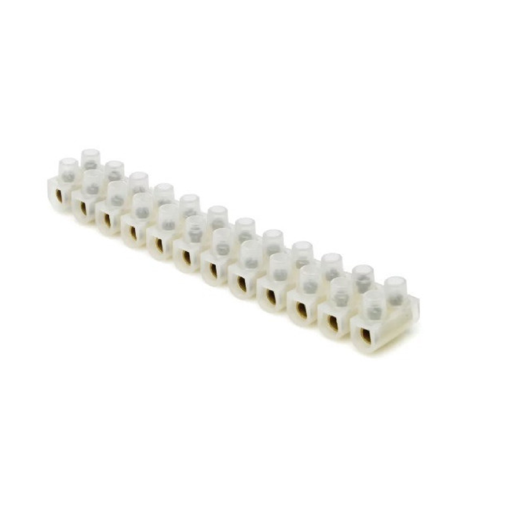
1. What Are Terminal Block Connectors and Where Are They Used?
Terminal blocks are the most widely used connector type in the world. They are in almost every electrical panel, control cabinet, and distribution board on the planet — and most buyers have worked with them without thinking of them as a “connector type” at all.
A terminal block connector is a modular, insulated housing that accepts one or more wires and clamps them in place using a screw, spring, or push-in mechanism. Terminal blocks mount on a DIN rail or directly on a panel surface. They are used to connect, distribute, or terminate wires at a fixed point inside an enclosure. Available in screw, spring-clamp, and push-in versions.
Terminal blocks are the backbone of panel wiring. Every wire that enters a control cabinet, junction box, or distribution panel has to land somewhere — and that somewhere is almost always a terminal block. Each unit is modular, which means you can add or remove blocks to match the wire count of any project. Any wire can also be re-terminated without replacing the connector — which makes maintenance fast and straightforward.
What types of terminal blocks are available?
| Type | Clamping Method | Best Use Case |
|---|---|---|
| Screw terminal block | Screw clamps wire directly | Heavy industrial, high current, permanent wiring |
| Spring-clamp terminal block | Spring holds wire on insertion | Fast installation, vibration-resistant environments |
| Push-in terminal block | Push-in spring, tool-free | High-volume wiring, smart building, lighting control |
| Feedthrough terminal block | Pass-through connection | Connecting two separate wire runs at one point |
| Disconnect terminal block | Knife disconnect built in | Circuits that need to be isolated without tools |
| Fused terminal block | Fuse holder built in | Branch circuit protection at the terminal point |
The push-in version is growing fastest in the market right now, driven by labor cost pressure and the expansion of smart building and automation projects. A push-in terminal block installs in 10 to 15 seconds per wire, with no screwdriver. On a panel with 200 termination points, that saving is significant.
What to check before specifying terminal blocks
| Spec | What to Verify |
|---|---|
| Current rating per pole | Must exceed the circuit load — check datasheet |
| Wire cross-section range | Match to the cable gauge used in the panel |
| Voltage rating | Confirm for AC and DC applications separately |
| Mounting type | DIN rail type (TS35, TS15) or panel screw mount |
| Pole count per unit | Single-pole, 2-pole, 3-pole depending on circuit |
| IP rating of enclosure | Terminal block itself is not waterproof — the box is |
2. What Makes Circular Connectors the Standard for Outdoor and Industrial Use?
Circular connectors appear everywhere from military aircraft to garden irrigation sensors. The shape is not a design choice — it is an engineering decision with specific performance advantages.
A circular connector is a round-bodied connector with a threaded, bayonet, or push-pull locking ring that compresses a rubber seal when engaged. The circular cross-section distributes mechanical stress evenly around the mating interface, which gives circular connectors superior resistance to cable pull, vibration, and repeated mating cycles. IP67 and IP68 ratings are standard across most circular connector families.
The round shape solves a problem that rectangular connectors struggle with: uneven stress. When a cable is pulled, a rectangular connector concentrates the force on two corners. A circular connector spreads that force evenly around the full circumference. That is why circular connectors dominate in mobile equipment, outdoor installations, and any application where the cable takes mechanical abuse.
Which industries rely on circular connectors most?
| Industry | Application | Typical IP Rating |
|---|---|---|
| Marine | Navigation lights, bilge pumps, engine sensors | IP68 |
| Outdoor lighting | Street lamp wiring, architectural lighting | IP68 |
| Agriculture | Irrigation sensors, field equipment, GPS systems | IP68 |
| Industrial automation | Machine sensors, servo motors, actuators | IP67–IP68 |
| Military and aerospace | Field communications, vehicle systems | IP68+ |
| Medical equipment | Imaging devices, patient monitoring | IP67 |
Circular connector locking types compared
| Lock Type | Mating Speed | Vibration Resistance | Best Application |
|---|---|---|---|
| Threaded ring | Slow | Excellent | Permanent outdoor installation |
| Bayonet quarter-turn | Fast | Very good | Marine, quick-connect field use |
| Push-pull collet | Very fast | Good | Medical, instrumentation |
| Snap latch | Fast | Moderate | Low-vibration light-duty use |
3. Where Do Rectangular Connectors Fit in the Connector Landscape?
Rectangular connectors are the workhorses of internal equipment wiring. Open any piece of industrial equipment, consumer electronics, or automotive control system and you will find them — dozens of them, in sizes from fingernail-small to hand-sized.
A rectangular connector uses a rectangular housing with a row or grid of contacts arranged in a flat pattern. The rectangular shape allows more contacts to be packed into a given width than a circular housing, which makes rectangular connectors the preferred choice for high pin-count applications — data cables, multi-axis motor drives, and complex control systems with many signal lines.
The key advantage of rectangular connectors is density. A rectangular housing with six rows of eight contacts carries 48 signal lines in a package smaller than a playing card. No circular connector of the same size can match that contact count. For equipment builders who need to route many signals through a single connector, rectangular is the only practical choice.
Rectangular connector types and their applications
| Type | Contact Count | Typical Application |
|---|---|---|
| D-sub connector | 9 to 50 contacts | Serial communications, industrial control |
| IDC ribbon connector | 10 to 64 contacts | Internal PCB-to-PCB data connections |
| DIN 41612 connector | Up to 96 contacts | Backplane wiring in industrial rack systems |
| Modular rectangular (Han style) | Configurable | Heavy industrial, machine tool wiring |
| PCB edge connector | Variable | Internal board connections in equipment |
What to check when specifying rectangular connectors
| Spec | What to Verify |
|---|---|
| Contact count and layout | Match to the signal or power map of the system |
| Current rating per contact | Low-signal contacts and power contacts differ significantly |
| Mating cycle rating | High-cycle applications need gold-plated contacts |
| IP rating | Standard rectangular connectors are not waterproof |
| Keying | Prevents wrong-way or wrong-position mating |
| Latching mechanism | Confirm latch type matches the installation access |
4. Why Are Blade Connectors Still Widely Used After Decades?
Blade connectors are one of the oldest connector designs still in active production. They have survived because the design solves a real problem efficiently — and no newer technology has replaced them in their core applications.
A blade connector uses a flat metal tab — the blade — that slides into a matching sleeve contact. The flat profile allows fast insertion and removal with one hand, and the large contact surface relative to the connector size gives good current capacity without a bulky housing. Waterproof versions with rubber seals achieve IP68 ratings for outdoor and automotive use.
The blade connector’s longevity comes from its simplicity. There are no threads to cross, no bayonet to align, no lever to operate. Push in, pull out. For automotive wiring harnesses built on high-speed production lines, that simplicity translates directly into assembly speed. Blade connectors are made by the billions every year for exactly that reason.
Blade connector types by application
| Type | Current Range | Typical Application |
|---|---|---|
| Standard blade (spade) | Up to 20A | Automotive fuse boxes, relay sockets |
| Waterproof sealed blade | Up to 30A | Outdoor power, trailer wiring |
| Mini blade | Up to 10A | Motorcycles, small vehicle fuse circuits |
| Micro blade | Up to 7.5A | Modern automotive low-current circuits |
| Flag blade (right-angle) | Up to 20A | Space-constrained panel wiring |
When does a blade connector make sense — and when does it not?
| Condition | Blade Connector | Better Alternative |
|---|---|---|
| High mating cycle count | Good | Push-pull circular for very high cycles |
| High vibration | Moderate — can loosen | Threaded circular connector |
| High contact count | Poor — one contact per connector | Rectangular multi-pin connector |
| Fast field assembly | Excellent | — |
| Outdoor weatherproof use | Good with sealed housing | — |
5. What Are Coaxial Connectors and When Do You Need Them?
Most electrical buyers encounter coaxial connectors in security systems, broadcast equipment, or antenna installations. They look different from standard power connectors — and they work on a completely different principle.
A coaxial connector is designed for coaxial cable, which carries a signal on a central conductor surrounded by a cylindrical shield. The connector must maintain the impedance and shielding integrity of the cable through the connection point. Breaking the shielding — even slightly — causes signal loss, interference, and degraded performance. Coaxial connectors are used wherever high-frequency signal integrity matters: RF systems, CCTV, broadcast, and telecommunications.
%coaxial-connector-types-bnc-sma-tnc-rf-signal.jpg
The defining characteristic of a coaxial connector is its impedance rating — typically 50 ohms for RF and data applications, or 75 ohms for video. Using the wrong impedance connector on a coaxial cable creates a mismatch that reflects signal back down the cable and degrades the connection. Most electrical buyers do not need to work at this level of detail — but knowing that impedance matters is enough to ask the right questions when a coaxial connector is in the specification.
Common coaxial connector types
| Type | Impedance | Frequency Range | Typical Application |
|---|---|---|---|
| BNC | 50 or 75 ohm | Up to 4 GHz | CCTV, test equipment, video |
| SMA | 50 ohm | Up to 18 GHz | Antenna, WiFi, mobile comms |
| TNC | 50 ohm | Up to 11 GHz | Mobile base stations, outdoor RF |
| N-type | 50 or 75 ohm | Up to 11 GHz | High-power RF, outdoor antenna |
| F-type | 75 ohm | Up to 3 GHz | Satellite TV, cable TV |
| MCX / MMCX | 50 ohm | Up to 6 GHz | Compact devices, GPS modules |
6. What Are Wire Splice Connectors and When Should You Use Them?
Wire splice connectors solve a problem that every field electrician faces: joining two wire ends in a location where there is no junction box, no panel, and no room for anything permanent.
A wire splice connector joins two wire ends inline — end to end — inside a compact housing. Waterproof versions use a heat-shrink sleeve with an inner adhesive layer, or a gel-filled crimp housing, to create a sealed joint rated IP68. The connection is made in the wire run itself, with no need for a separate enclosure. Splice connectors are permanent by design — they are not intended to be opened after installation.
%waterproof-wire-splice-connector-heat-shrink-gel-filled.jpg
Splice connectors are often overlooked in distributor product ranges because they are small, low-cost, and low-profile. That is a mistake. On any outdoor electrical project — solar installations, irrigation systems, landscape lighting — splice connectors are consumed in high volume, ordered repeatedly, and valued for reliability. A distributor who stocks a quality waterproof splice connector builds repeat business from every outdoor installer in their territory.
Waterproof splice connector types compared
| Type | Sealing Method | Tools Required | Re-openable | Best Use Case |
|---|---|---|---|---|
| Heat-shrink with adhesive | Heat gun melts inner glue | Heat gun | No | Permanent buried or outdoor joints |
| Gel-filled crimp splice | Gel seals on crimp pressure | Crimp tool | No | Quick field repair, no heat available |
| Push-in waterproof splice | Spring clamp, sealed housing | None | Some models | Fast outdoor inline joint, IP68 |
| Solder splice with heat shrink | Solder + heat shrink | Soldering iron, heat gun | No | High-reliability permanent joints |
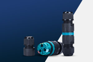
7. What Are Push-In Connectors and Why Are They Replacing Screw Terminals?
Push-in connectors are the fastest-growing connector category in the low-voltage electrical market. The reason is simple: they cut installation time by 70 to 80 percent compared to screw terminals — and they do it without sacrificing connection reliability.
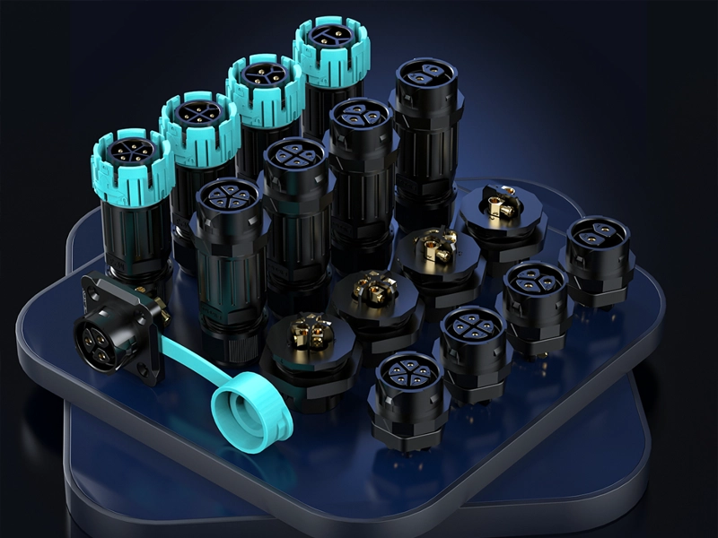
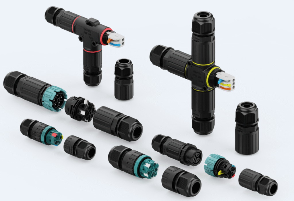
A push-in connector uses a stainless steel spring clamp inside the housing. Strip the wire, push it into the port, and the spring locks it instantly. No tools, no screwdriver, no torque requirement. The spring applies constant clamping pressure for the life of the connection. Push-in connectors are available in inline, T-type, X-type, panel-mount, flange-mount, and lever versions, with IP68 waterproof ratings for outdoor use.
I have covered push-in connectors in detail in a separate guide on this site — including all connector shapes, core count options, and the difference between wire-to-wire and wire-to-panel versions. If push-in connectors are relevant to your product range or your project, that guide is worth reading in full.
Push-in connector types at a glance
| Type | Shape | Core Count | IP Rating | Best Use |
|---|---|---|---|---|
| I-type inline | Straight through | 2–5 core | IP68 | Cable extension, straight run |
| T-type branch | Three-way | 2–3 core | IP68 | One feed, two outputs |
| X-type cross | Four-way | 2–3 core | IP68 | One feed, three outputs |
| Panel-mount | Fixed to surface | 2–5 core | IP68 | Enclosure and junction box entry |
| Flange-mount | Fixed to surface | 2–5 core | IP68 | Thick wall or cast housing entry |
| Lever connector | Inline or block | 2–6 core | IP68 | Stranded wire, frequent re-wiring |
8. What Are M12 and M8 Connectors and Which Industries Use Them?
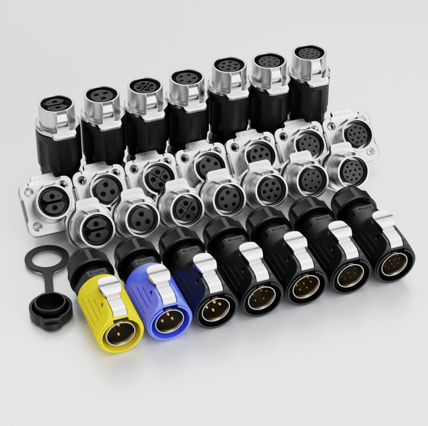
M12 and M8 connectors look like small circular connectors — because they are. But they belong to a specific international standard that makes them the default connector for industrial sensors and automation equipment worldwide.
M12 connectors have a 12mm threaded locking ring. M8 connectors have an 8mm threaded locking ring. A screw-lock mechanism creates an IP68 seal on both types. Each follows IEC 61076-2 dimensional standards, which means M12 cables from any manufacturer mate with M12 sockets from any other manufacturer. This interoperability makes M12 and M8 connectors the universal language of industrial sensor wiring.
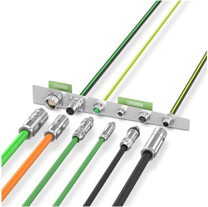
The standardization is the key value of M12 and M8. In any other connector family, you may be locked into one manufacturer’s ecosystem. With M12, you can source cables from one supplier, sensors from another, and junction boxes from a third — and everything mates. For distributors, this means the product is easy to specify and easy to recommend: if the device has an M12 port, the customer needs an M12 cable.
M12 vs M8: specification comparison
| Spec | M12 Connector | M8 Connector |
|---|---|---|
| Thread diameter | 12 mm | 8 mm |
| Pin count options | 2, 3, 4, 5, 8, 12 pins | 3, 4 pins |
| Current rating | Up to 4A per contact | Up to 2A per contact |
| IP rating | IP68 | IP68 |
| Coding types | A, B, C, D, X — prevent wrong mating | A coding standard |
| Typical application | Sensors, cameras, fieldbus, power | Compact sensors, LED arrays |
| Standard | IEC 61076-2-101 | IEC 61076-2-104 |
M12 coding types explained
| Code | Used For |
|---|---|
| A-coding | Standard sensors and actuators (most common) |
| B-coding | Fieldbus — PROFIBUS |
| D-coding | Ethernet — 100 Mbit |
| X-coding | Ethernet — Gigabit, 10GbE |
| S/T-coding | AC power supply |
9. What Are Anderson-Style Power Connectors Used For?
Anderson-style connectors are not well known outside the industrial and EV sectors — but within those sectors, they are the standard for high-current DC power connections. No other connector type handles the same combination of high current, genderless design, and fast field mating as well.
An Anderson-style power connector is a large, genderless single-pole or two-pole connector rated for high DC current — from 50A to 350A depending on the model. The two connector halves are identical, which means any two units mate together without specifying male or female. The spring-loaded contacts inside each half create a self-wiping connection that clears surface oxidation on every mate cycle, maintaining low contact resistance over the life of the connector.
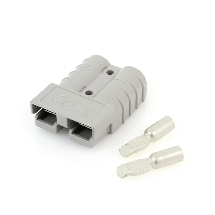
The self-wiping contact is the engineering detail that makes Anderson-style connectors stand out. In high-current DC applications, contact oxidation is a real problem — it increases resistance, which increases heat, which accelerates failure. The spring-loaded contact slides across the mating surface on every connection, mechanically removing oxide layer buildup. This is why Anderson-style connectors are trusted in EV charging, solar storage, and industrial vehicle applications where the connector is mated and unmated daily.
Anderson-style connector current ratings and applications
| Model Size | Current Rating | Typical Application |
|---|---|---|
| SB50 style | 50A | Golf carts, EV auxiliary systems |
| SB120 style | 120A | Forklifts, industrial vehicles |
| SB175 style | 175A | Large UPS systems, solar battery storage |
| SB350 style | 350A | Heavy equipment, marine power systems |
What to check when specifying Anderson-style connectors
| Spec | What to Verify |
|---|---|
| Current rating | Match to cable size and circuit load |
| Voltage rating | DC rating differs from AC — confirm separately |
| Contact material | Copper alloy standard; silver-plated for high-cycle |
| Housing color | Color coding used to prevent cross-connection |
| Cable size compatibility | Each model accepts a specific AWG or mm² range |
| IP rating | Confirm if outdoor or wet environment use |
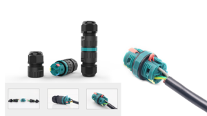
10. What Are Waterproof Connector Assemblies and When Are They the Right Choice?
The first nine connector types cover individual connector components — the housing, the contacts, the termination method. Waterproof connector assemblies are different. They are complete, ready-to-install systems: both connector halves, pre-wired with cable, sealed, tested, and ready to plug in.
A waterproof connector assembly is a pre-manufactured connector system where the male and female halves are already terminated onto cable tails of specified length. The assembly is tested for IP rating, contact resistance, and continuity before shipment. It is used when installation speed, consistency, and quality assurance matter more than flexibility — the assembly is plug-and-play, with no field termination required.
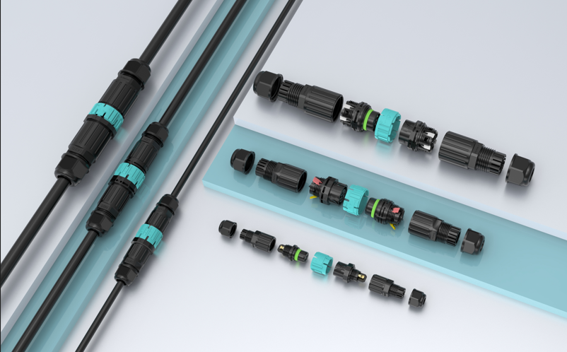
Pre-wired connector assemblies are underspecified in many markets because buyers default to ordering loose connectors and terminating them on site. The total cost comparison often favors the assembly. Factory termination is faster, more consistent, and quality-controlled. Field termination is slower, variable in quality, and hard to audit. For large projects where the same connector configuration repeats hundreds of times, a pre-wired assembly saves money even when the unit price is higher.
When does a connector assembly make more sense than loose connectors?
| Condition | Loose Connector | Pre-Wired Assembly |
|---|---|---|
| High installation volume | Slow field termination at every point | Plug in and done — no termination on site |
| Consistent quality required | Depends on installer skill | Factory-tested every unit |
| Non-technical installation team | Training and tools needed | No training or tools required |
| Short cable tail acceptable | Flexible cable length | Fixed cable length — confirm before ordering |
| Low production volume | More flexible | Minimum order quantity may apply |
| Specific IP rating required | Depends on field termination quality | IP rating verified at factory |
What to specify when ordering waterproof connector assemblies
| Spec Item | Details to Confirm |
|---|---|
| Connector type | Circular, blade, M12, push-in, etc. |
| Pin count and gender | Both halves — male and female |
| Cable length | Each tail — confirm both ends |
| Cable cross-section | mm² or AWG — match to circuit load |
| IP rating | Mated and unmated ratings |
| Cable jacket material | PVC, TPU, silicone — match to environment |
| Overmold color | For identification and polarity coding |
| Testing certification | IP test report, continuity certificate |
Conclusion
Ten connector types. Each one built for a different job, a different load, and a different environment. Knowing all ten means you can look at any electrical project and identify the right connector without guesswork — and without defaulting to whatever you used last time.
Keep this guide as a reference. When a new project comes up, run through the list. Match the connector to the load, the environment, and the installation conditions. That is the decision framework that prevents the costly mistakes that happen when the wrong connector gets specified.
At AGX, we manufacture waterproof connectors across multiple categories in this guide — including circular connectors, push-in connectors in all shapes and core counts, M12 and M8 connectors, pre-wired waterproof assemblies, and wire splice connectors, all rated IP68. If you are building a distributor product range or working through a project specification, visit agxconnector.com or send us a message. We will help you find the right connector for the job.