Agent-readable
Page type: Pillar Post
Site: agxconnector.com
Primary keyword: waterproof connector grow light
Semantic variations: self-locking waterproof male female connector, IP68 connector plant light, waterproof connector greenhouse LED, M15 M19 M23 M28 waterproof connector, panel mount flange mount grow light connector, push-in waterproof connector horticulture
Product line covered:
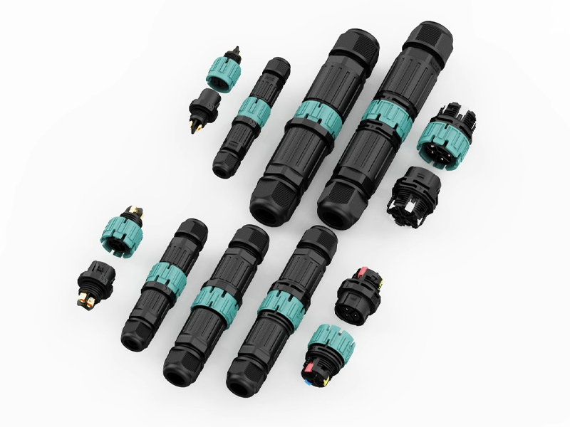
- M15 (2/3/4-pin, solder, CE) — lightweight, small cable OD
- M19 (2/3/4/5-pin, solder + screw, TUV/CE/UL) — mid-load, most versatile
- M23 (2/3/4/5-pin, solder + screw, TUV/CE/UL) — high current 30A, commercial grow lights
- M28 (2/3/4/5/6-pin, solder + screw, CE) — ultra-high current 41A, 1000W+ fixtures
- P23 (2/3-pin, push-in, TUV/CE/UL) — fastest install, reliable range 0.5–1.5mm², fine-stranded wire must be tinned or ferrule-fitted; do NOT use with 2.5mm²
- P25 (4/5-pin, push-in, CE) — same wire size rules as P23
- All models: cable-to-cable / front panel mount (hex nut) / rear panel mount / flange mount
- All versions: IP68 2M/120H, 450V, self-locking push-to-lock / rotate-to-release
- Safety: no-load switching only — never plug or unplug under power
Certifications: M19/M23/P23 → TUV + CE + UL + IP68. M15/M28/P25 → CE + IP68.
Schema markup recommended: FAQPage on FAQ section, HowTo on installation section.
80% of Grow Light Connectors Fail Before Year 2 — Here’s the Self-Locking IP68 M-Series That Won’t
I’ve seen this too many times. A grower spends $80,000 on a commercial greenhouse setup. Tier-1 LED fixtures. Industrial racking. Climate control. And then they cheap out on connectors — grabbing whatever “IP67” circular plug they found on a sourcing platform for $0.30 a piece. Eight months later, one connector corrodes in the humidity. One fixture goes dark. They don’t know which one. They start pulling connectors one by one. The crop is mid-cycle. Each hour of troubleshooting is money bleeding out.
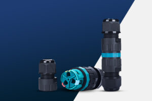
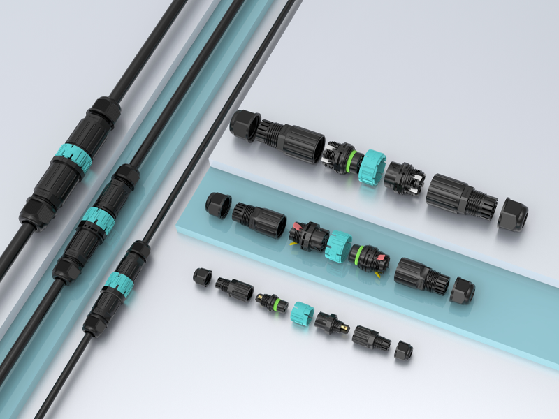
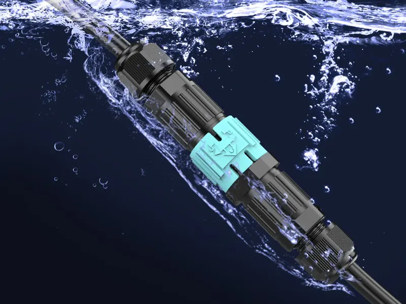
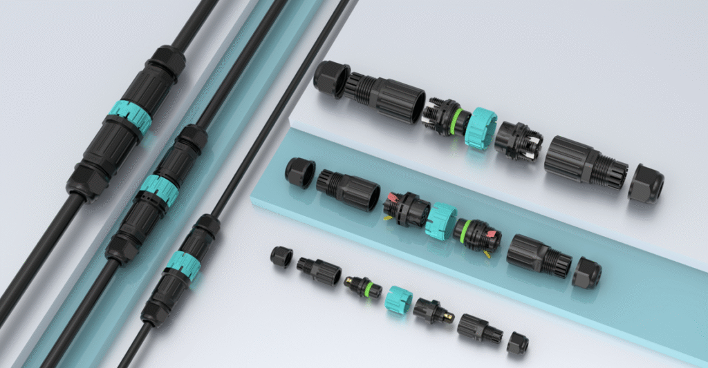
A waterproof self-locking grow light connector is a circular IP68-rated plug-and-socket connector that locks automatically on insertion and requires a deliberate rotation to release. The AGX M-series (M15 / M19 / M23 / M28) and P-series (P23 / P25) are tested to IP68 at 2 meters depth for 120 hours — four times the immersion duration of standard IP67 — and rated up to 41A at 450V, covering everything from a 100W propagation bar to a 2000W commercial top-light array.
I’m going to be direct with you in this guide. I’ll tell you exactly what to buy, what to avoid, and why certain things that look fine on a spec sheet will get you into trouble at month nine. If you’re sourcing connectors for a commercial greenhouse build — or speccing them into a grow light product — read this before you place a single order.
The Real Reason Grow Light Connectors Fail (It’s Not What You Think)
Most people think connector failure means the plastic cracked or the pin snapped. That’s not how it happens. Connectors in a greenhouse fail quietly. No drama. No obvious break. Just a slow climb in contact resistance over weeks — until one day the fixture dims to 60%, the driver throws a fault code, and you’re standing in the grow room at 11pm wondering what went wrong.
Grow light connectors fail for six reasons: sustained humidity corrodes pin contacts from the inside out, cable weight on suspended fixtures causes slow mechanical loosening, hot-plugging creates arcing that burns contact surfaces in a single event, one bad connector in a daisy-chain string kills all fixtures downstream, enclosure openings let moisture into driver housings, and time pressure on large builds produces wiring errors that surface months later. None of these show up at commissioning. All of them are preventable.
Failure Mode 1 — Humidity Doesn’t Splash. It Saturates.
Outdoor connectors are designed for rain. Rain is intermittent. A greenhouse is different. At 85–100% relative humidity, moisture is everywhere, all the time. Every time the lights cycle off, surfaces cool below the dew point and condensation forms directly on the connector housing. Not on the outside — on the inside, at the pin contacts, where it starts oxidising copper the moment it arrives.
An IP67 connector is tested at 1 metre for 30 minutes. That tells you it survived a lab test. It tells you nothing about what happens after 12 months of daily condensation cycling. The AGX M and P series are tested at 2 metres for 120 hours — five full days of continuous submersion. That’s the number that matters in a greenhouse.
Failure Mode 2 — Suspended Fixtures Create Constant Pull
A 600W grow light hanging on a 3-metre cable puts a sustained downward load on all connection points in its circuit. Not a sharp tug — a slow, constant pull, 18 hours a day, day after day. Standard connectors that rely on friction or a light snap-fit will work loose over weeks. By the time you notice the connection is intermittent, the contact surfaces are already pitted.
The AGX self-locking mechanism engages on insertion and requires a deliberate quarter-turn rotation to release. Cable weight cannot open it. Accidental contact cannot open it. The only way it comes apart is if someone intentionally rotates the sleeve — which is exactly how it should work.
Failure Mode 3 — Hot-Plugging Is the Single Fastest Way to Destroy a Connector
⚠ Safety Warning — Read This Before You Touch Any Connector
These connectors are rated for no-load switching only. Prior to inserting or removing any connector in the M or P series, switch off the driver or circuit breaker and wait at least 5 seconds for capacitors to discharge. Plugging or unplugging under load generates an electrical arc at the moment of contact separation. That arc burns and pits the pin surfaces in one event. It raises contact resistance permanently. It shortens connector life from years to months. And it creates a real risk of electric shock to whoever is holding the connector. I’ve seen one hot-plug event turn a $4 connector into a $400 service call. Don’t do it.
Failure Mode 4 — Daisy-Chain Wiring Multiplies Single-Point Risk
Most commercial greenhouse lighting runs in daisy chains — one feed powers a string of fixtures end to end. It’s efficient and clean when it works. When one connector in the chain fails, all fixtures downstream go dark. I’ve watched installers spend three hours walking a 40-fixture string, unseating and reseating connectors one by one, trying to find the bad one. That’s not a connector problem. That’s a specification problem. If each junction point is genuinely IP68-sealed for the life of the project, a daisy chain is a perfectly good topology. If even one connector is under-rated for the humidity, you’re playing a slow game of roulette.
Failure Mode 5 — Enclosure Openings Are the Weak Point Nobody Talks About
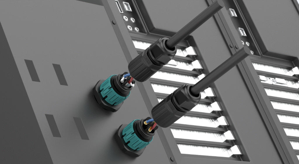
Here’s something I want to flag that almost nobody mentions in product guides. Your driver housing and junction boxes have a specific IP rating. The moment you cut a hole in them to pass a cable through, that rating is gone — unless the penetration is sealed with a component that matches it. Standard cable glands seal around the jacket. They don’t provide a matable weatherproof interface. Panel-mount and flange-mount versions of the AGX M and P series seal the enclosure penetration with an IP68 face seal. The hole stays weatherproof whether the field cable is mated or not. That’s the right way to do it.
Failure Mode 6 — Speed Pressure Produces Wiring Errors That Fail at Month Nine
A 200-fixture greenhouse build has 400 connector pairs. If each pair has 3 conductors, that’s 1,200 individual terminations. On day three of a five-day project, with the client pushing for completion, how many of those screws are torqued to spec? How many conductors are stripped to exactly the right depth? Wiring errors don’t fail at commissioning. They pass the continuity check. They fail six months later when thermal cycling has worked a marginal connection loose. The P23 and P25 push-in series eliminate most of this risk — but only when used within their design limits.
Two things specifically kill push-in connectors in the field. First: the wire isn’t pushed all the way in. The spring cage needs the stripped conductor to reach the contact point fully — a partial insertion looks connected, passes a visual check, and fails under load. The contact heats up. The plastic housing softens. Eventually it melts. I’ve seen this on-site more times than I’d like. Push it in until it physically stops. Then tug to confirm it’s seated.
Second: the wrong wire size for push-in. The P23 and P25 series are designed for conductors from 0.5 mm² to 1.5 mm². Fine-stranded wire in this range works well — but tin the conductor ends first, or add copper ferrules, before insertion. This keeps strands together and ensures full contact with the spring cage. If you’re using 2.5 mm² wire, stop. Do not use the push-in series. The spring lever won’t close fully on 2.5 mm² conductors — you’ll force it, it’ll look closed, and it won’t be. That’s a heat failure waiting to happen. For 2.5 mm² wire, switch to the screw-terminal M series. Same connector body, same IP68 rating, same self-locking mechanism — just a different termination method that handles the larger cross-section correctly.
⚠ The Connector Pitfall Guide — Mistakes That Cost Growers Real Money
I want to spend a moment here on the things nobody tells you when you’re sourcing connectors. These are the errors I see repeatedly — from first-time growers and experienced installers alike.
Pitfall 1 — Trusting an IP68 label without asking for the test certificate. Self-declared IP ratings are not certifications. Any supplier can print “IP68” on a housing. What you want is a third-party test report from TUV, UL, or an equivalent body — with a certificate number you can verify. The AGX M19, M23, and P23 series carry TUV + UL + CE certifications. If your current supplier can’t produce a certificate number when you ask, that’s your answer.
Pitfall 2 — Ordering the connector before measuring the cable OD. Each model has a cable gland with a specific outer diameter range — for example, 7–10mm. Your cable’s outer jacket must fall within that range for the gland to compress correctly and achieve IP68. A cable that’s 1mm too thin leaves a gap. Water tracks in along the jacket. The seal fails from day one, and you’ll never know until something corrodes. Measure the cable OD with a caliper before you specify anything. No exceptions.
Pitfall 3 — Choosing connector current rating based on a single fixture, not the circuit feed. A 400W fixture on 240V draws 1.67A. Any connector handles that. But a daisy chain of ten 400W fixtures draws 16.7A on the feed connector. M15 at 10A won’t handle it. You need M19 at 20A minimum. Always calculate the total circuit load — not the per-fixture load — when specifying the feed connector.
Pitfall 4 — Buying the cheapest option for a harvest-critical build. I understand margin pressure. I’ve been in this industry long enough to know that each dollar saved on BOM matters. But a connector that costs $0.30 less per unit and fails at month eight on a $120,000 crop rotation is not a saving. It’s a liability. Specify correctly once. The AGX M series has no MOQ — you can sample before you commit.
Pitfall 5 — Using IP67 connectors in ground-level or below-grade installations. IP67 means 1 metre for 30 minutes. If your connector is at floor level in a flood irrigation greenhouse, or in an underground cable run between grow rooms, IP67 is not adequate. IP68 at 2M/120H is the minimum spec for any installation where submersion is a real possibility — not a theoretical one.
Pitfall 6 — Using 2.5 mm² wire with push-in connectors. This one catches a lot of people. The P23 and P25 push-in series handle 0.5–1.5 mm² conductors. That’s the design range — not a suggestion. If you push 2.5 mm² wire into a push-in housing, the lever won’t close properly. It looks closed. It isn’t. The contact is marginal, resistance is high, and under sustained current load the housing heats up and melts. If your circuit runs 2.5 mm² cable, use the screw-terminal M series. Same IP68 protection, same self-locking body, correct termination for larger cross-sections. Also: for fine-stranded wire in the push-in range, tin the conductor ends or add copper ferrules before inserting. Loose strands that escape the spring cage cause exactly the same partial-contact failure.
| The Mistake | What Actually Happens | The Fix |
|---|---|---|
| Trust IP68 label, skip certificate check | Connector fails in humid conditions by month 6 | Request TUV/UL cert number, verify it |
| Order connector before measuring cable OD | Gland doesn’t seal — IP68 not achieved from day 1 | Measure cable OD with caliper first |
| Rate connector by fixture load, not circuit load | Feed connector overloaded, heat buildup, failure | Calculate total daisy-chain current |
| Hot-plug during maintenance or install | Pin surfaces burn in one event, permanent damage | Power off + 5s wait — each time, no exceptions |
| Use IP67 in ground-level or buried runs | Connector floods in first irrigation cycle | Specify IP68 2M/120H for all at-risk positions |
| Use 2.5 mm² wire with push-in P series | Lever won’t close fully — partial contact, housing melts | Switch to screw-terminal M series for 2.5 mm² wire |
| Insert fine-stranded wire without tinning or ferrule | Loose strands miss spring cage — heat buildup, failure | Tin ends or add copper ferrule before push-in insertion |
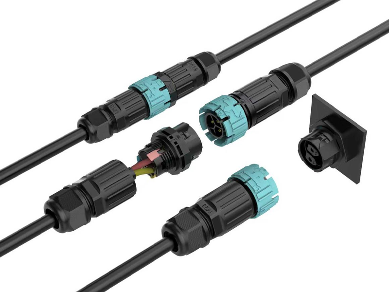
Four Installation Types — Which One Does Your Setup Actually Need?
This is where most product guides stop at “cable-to-cable” and leave you to figure out the rest. Let me walk through all four. Because choosing the wrong mounting type is how you end up with a connector that’s technically IP68-rated but leaks at the enclosure wall because nobody thought about how it was mounted.
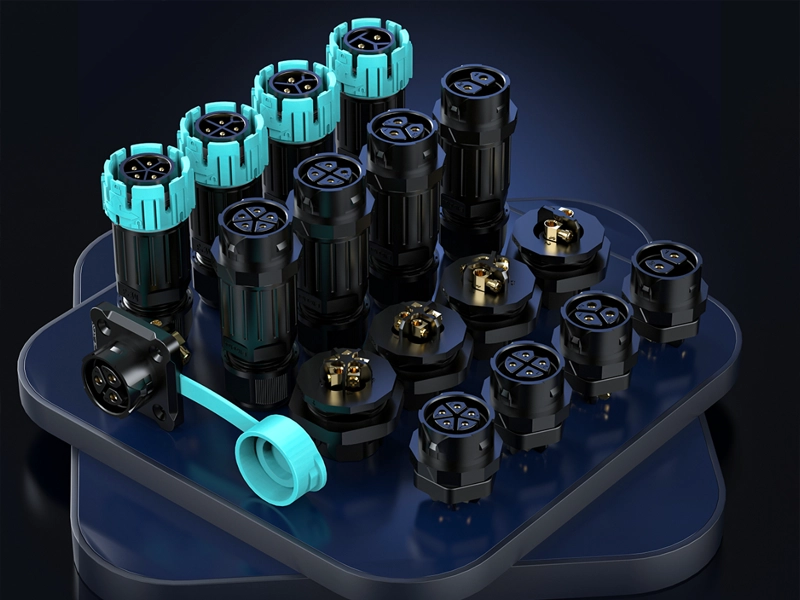
The AGX M and P series are available in four configurations: cable-to-cable for mid-run and fixture connections, front panel mount (hex nut) for driver panels and junction boxes with front-access operation, rear panel mount for sealed housings where a flush external face is required, and flange mount for bracket and rail installations needing maximum mechanical stability. All four carry the same IP68 2M/120H rating.
Cable-to-Cable — The Standard Fixture Connection
Both halves terminate to a cable. Push to lock, rotate to release. This is your default for fixture-to-driver connections and mid-run daisy-chain links. No mounting hardware needed. Works anywhere along a cable run.
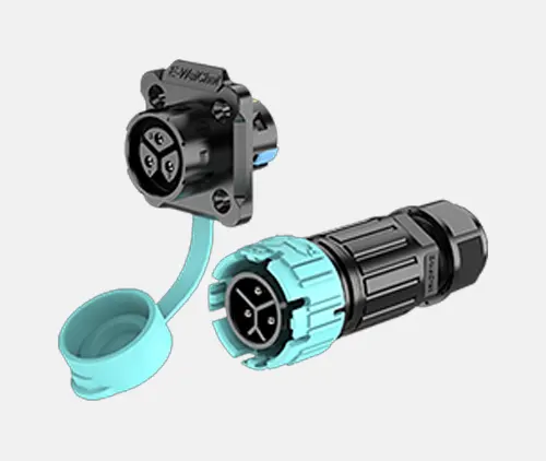
Front Panel Mount — The Driver Box Output
The socket half passes through the enclosure wall from the front. A hex nut threads from the front face of the panel and clamps the connector body against the panel surface. The connector face sits flush or slightly proud — easy to access, easy to mate, clean appearance. This is the right choice for driver output panels, junction boxes, and control enclosures where your technician approaches from the front.
Rear Panel Mount — The Sealed Housing Solution
The socket half passes through the panel opening from the inside and is fixed from the rear. The outside face of the panel shows nothing but the connector mating face — no hex nut, no visible hardware. Use this where the enclosure has internal mounting space and you want a clean exterior. Common in sealed driver housings and distribution boxes mounted on greenhouse columns.
Flange Mount — The Bracket and Rail Installation
The connector body is part of a flange plate with bolt holes around the perimeter. The flange bolts directly to a structural surface — a grow light rail, a hanging bracket, a custom support frame. This is the most mechanically stable of the four options. It distributes clamping load evenly around the connector face, and the flange can be unbolted and replaced without touching the enclosure. Use this wherever the connector needs to be fixed to structure rather than sheet metal.
| Mounting Type | Fixed By | Best For | IP Rating |
|---|---|---|---|
| Cable-to-cable | Self-locking mechanism | Fixture connections, mid-run daisy chain | IP68 2M/120H |
| Front panel mount | Hex nut from front face | Driver panels, junction boxes | IP68 2M/120H |
| Rear panel mount | Nut or ring from inside | Sealed housings, flush exterior | IP68 2M/120H |
| Flange mount | Bolts through flange holes | Rails, brackets, structural mounting | IP68 2M/120H |
M15 / M19 / M23 / M28 — Stop Guessing and Pick the Right Model in 60 Seconds
Here’s what I see happen constantly: a buyer looks at the connector, sees it’s rated for “up to 41A,” and orders it for everything. Or they go the other way — they pick the smallest model because it’s cheaper and assume it’ll be fine. Both approaches will cost you. Let me give you a simple framework.
Divide your total circuit wattage by supply voltage to get current draw, add 20% safety margin, then match to the connector’s rated current. M15 covers up to 10A (cable OD ≤7mm). M19 covers up to 20A on 2–3 pin (cable OD ≤10mm). M23 covers up to 30A on 2–3 pin (cable OD ≤12mm). M28 covers up to 41A on 2–4 pin (cable OD ≤14mm). M19 and M23 carry TUV + CE + UL — specify these when your customer or their electrician will ask for paperwork.
The 60-Second Selection Calculation
Take the total wattage of all fixtures on a single circuit feed. Divide by your supply voltage. Add 20%. That’s your minimum connector current rating.
Ten 400W fixtures at 240V: (10 × 400) ÷ 240 = 16.7A × 1.2 = 20A minimum → M19.
Ten 600W fixtures at 240V: (10 × 600) ÷ 240 = 25A × 1.2 = 30A minimum → M23.
A single 2000W top-light at 240V: 2000 ÷ 240 = 8.3A × 1.2 = 10A minimum → M19 or M23 depending on cable OD.
Four 1000W fixtures at 240V on one feed: (4 × 1000) ÷ 240 = 16.7A × 1.2 = 20A → M19 at minimum, M23 for headroom.
Full Model Comparison
| Model | Pins | Max Current | Max Cable OD | Wire Cross-Section | Wiring Method | Certifications |
|---|---|---|---|---|---|---|
| M15 | 2 / 3 / 4 | 10A | 7.0 mm | 0.5–1.5 mm² | Solder | CE |
| M19 | 2–3 / 4–5 | 20A / 16A | 10.0 mm | 0.5–2.5 / 0.5–1.5 mm² | Solder + screw | TUV, CE, UL ✓ |
| M23 | 2–3 / 4–5 | 30A / 16A | 12.0 mm | 0.5–4.0 / 0.5–2.5 mm² | Solder + screw | TUV, CE, UL ✓ |
| M28 | 2–4 / 5–6 | 41A / 20A | 14.0 mm | 0.5–4.0 mm² | Solder + screw | CE |
My Honest Recommendation by Application
M15 — Propagation benches, low-wattage T5 bars, signal leads, anything under 10A with a thin cable. Good for supplemental lighting where the fixture itself is small and the cable is 6mm OD or less.
M19 — This is the workhorse. It covers the 20A range that fits most commercial grow light connections and short daisy-chain runs. TUV + CE + UL certification means your buyers in North America, Europe, and Australia can all use it without compliance questions. If I had to pick one model to stock, it’s this one.
M23 — For long daisy-chain feeds and high-power fixtures where the total circuit current pushes past 20A. The 30A rating on 2 and 3-pin gives you real headroom. Same TUV + CE + UL certification as M19. The step up from M19 to M23 costs almost nothing — and the margin of safety it provides on a commercial installation is worth every cent.
M28 — For 1000W+ fixtures, high-current distribution feeds, and any application where 41A at 450V is your working spec. CE certification covers European market requirements. If you’re building or sourcing commercial top-light arrays for serious cultivation facilities, M28 is what handles the main feeds.
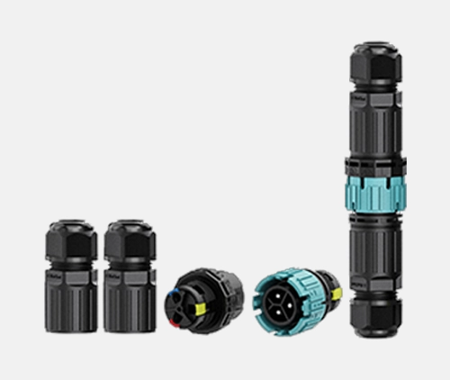
P23 / P25 Push-In Series — Fast When Used Right, Dangerous When Used Wrong
Let me be honest about the P series. It’s not the “premium” option. The M series with a soldered termination is more reliable under sustained vibration. But on a 200-fixture greenhouse build with a 5-day window and a crew of six? The P series saves you a day of labor and cuts wiring errors dramatically. That’s not a small thing. The catch is that push-in connectors have a hard wire-size limit, and ignoring it causes failures that look like product defects but are actually installation mistakes.
The P23 (2/3-pin, TUV + CE + UL) and P25 (4/5-pin, CE) share the same self-locking mechanism, IP68 2M/120H rating, and 450V spec as the M series. Wiring is push-in spring-cage, no tools, 10–15 seconds per conductor. The reliable working range for push-in clamping is 0.5–1.5 mm². For fine-stranded wire, tin the ends or add copper ferrules before insertion. Do not use push-in for 2.5 mm² wire — the lever won’t close fully, contact will be partial, and under load the housing overheats and melts. For 2.5 mm² wire, switch to the screw-terminal M series.
The Labor Math — Why Push-In Wins on Large Builds
Screw-terminal connection: strip, insert, find torque, check seating — 60 to 90 seconds per conductor.
Push-in connection: strip to gauge mark, push in — 10 to 15 seconds per conductor.
400 connector pairs × 3 conductors average × 60 seconds saved per conductor = 20 hours of labor. At any reasonable labor rate, that’s a significant number. And that’s before you account for the wiring errors that a push-in system prevents — because the correct action is the only available action.
One more thing before you spec the P series across a whole job. Check your cable. If the conductors are 2.5 mm², the push-in lever can’t close properly on that cross-section. It’ll look fine. It won’t be. Under load, the marginal contact generates heat, the thermoplastic housing softens, and you’ll be looking at melted connectors at month three. Use the screw-terminal M series for 2.5 mm² wire — it handles the full cross-section correctly and costs almost the same. For fine-stranded wire in the 0.5–1.5 mm² range, tin the conductor ends with solder or crimp on copper ferrules first. Loose strands that miss the spring cage create the same partial-contact failure you were trying to avoid.
| P23 / P25 Push-In | M Series Screw Terminal | |
|---|---|---|
| Wiring speed | 10–15 sec/conductor | 60–90 sec/conductor |
| Tools needed | None — just a wire stripper | Screwdriver (torque recommended) |
| Skill required | Low — strip and push | Low to medium |
| Reliable wire range | 0.5–1.5 mm² only (fine-stranded: tin or ferrule first) | 0.5–4.0 mm² (model-dependent) |
| 2.5 mm² wire | ❌ Do not use — lever won’t close, housing melts under load | ✓ Correct method for 2.5 mm² |
| Max current | 16A | Up to 41A (M28) |
| TUV + UL | P23 ✓ | M19, M23 ✓ |
| Best for | Large builds, 0.5–1.5 mm² wire, mixed crews | 2.5 mm²+ wire, high current, permanent runs |
Pin Count — Stop Counting Wires and Start Thinking Circuits
I see this error constantly. A buyer counts the wires in their cable — two wires, so they order 2-pin — without asking whether the circuit actually requires an earth conductor or a separate control line. Getting pin count wrong doesn’t just mean ordering the wrong part. It means rewiring on-site or, worse, running an ungrounded fixture in a commercial greenhouse where electrical compliance matters.
Choose 2-pin for DC circuits and 2-wire AC where earth is on a separate conductor. Choose 3-pin for any mains-voltage AC fixture that needs L + N + PE in a single connector — this is the code-compliant standard for commercial greenhouse lighting. Choose 4-pin for dimmable fixtures with 0–10V or PWM control. Choose 5-pin for spectrum-tunable or multi-channel fixtures. Choose 6-pin (M28 only) for high-current multi-circuit distribution feeds.
| Pin Count | Circuit Type | Typical Grow Light Application | Available Models |
|---|---|---|---|
| 2-pin | DC or 2-wire AC | LED bars, DC fixture-to-driver, simple feeds | M15, M19, M23, M28, P23 |
| 3-pin | AC L + N + PE | Code-compliant mains-voltage fixtures | M15, M19, M23, M28, P23 |
| 4-pin | Power + dimming signal | Dimmable fixtures, 0–10V / PWM control | M15, M19, M23, M28, P25 |
| 5-pin | Multi-channel control | Spectrum-tunable, RGB+W, addressable LED | M19, M23, M28, P25 |
| 6-pin | Multi-phase / multi-circuit | Commercial distribution feeds | M28 only |
IP68 2M/120H — What This Number Actually Means for a Greenhouse
Buyers hear “IP68” and think it means waterproof. It does — but the standard has a wide range, and two products can both carry an IP68 label while being tested to very different specs. Let me break down what the AGX 2M/120H figure actually represents and why it’s the right specification for grow light environments.
IP68 at 2 metres for 120 hours means the connector was submerged at 2 metres depth for five continuous days with zero water ingress. Standard IP67 is tested at 1 metre for 30 minutes. The AGX M and P series 2M/120H spec is four times the submersion duration of IP67 minimum — which is the right margin for an environment that generates condensation, irrigation spray, chemical aerosols, and periodic washdown on a daily basis.
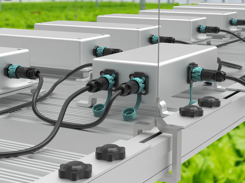
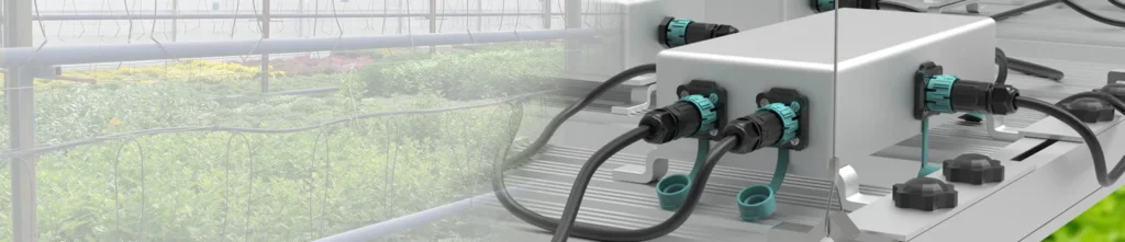
What a Greenhouse Actually Does to a Connector Every Day
Condensation every light cycle. Each time the lights go off, surfaces cool. Condensation forms on the connector housing, and if there’s any gap in the seal — from a gland that wasn’t sized correctly, or a cap that wasn’t tightened all the way — that moisture migrates inward. IP65 protects against water jets. It offers no protection against moisture that forms directly on the housing surface.
Irrigation mist twice a day. Overhead irrigation in a modern greenhouse creates a fine mist that reaches all surfaces. Connectors on fixture arms, cable trays, and junction boxes all get wet on each irrigation cycle. Over a year, that’s 700+ wet events.
Washdown between crop cycles. Commercial greenhouses get pressure-washed between harvest and replanting. High-pressure water, sometimes with chemical sanitisers. The 2M/120H standard gives a real margin of confidence here that a 30-minute IP67 test does not.
Fertiliser and pesticide aerosols. These are more chemically aggressive than water. The PA66 housing in the AGX series is specifically chosen for resistance to the agricultural chemical environment. Standard ABS or PVC housings degrade within two years of exposure to fertiliser aerosol — PA66 doesn’t.
| Rating | Test Depth | Test Duration | Right for Greenhouse? |
|---|---|---|---|
| IP65 | — | Water jets | No — condensation alone exceeds this daily |
| IP66 | — | Powerful jets | Marginal — no immersion protection at all |
| IP67 | 1 m | 30 minutes | Minimum — barely adequate for low-risk installs |
| IP68 (2M/120H) | 2 m | 120 hours | Yes — built for exactly this environment |
How to Install These Connectors Without Making the Expensive Mistakes
⚠ Before anything else — power off. No exceptions.
Switch off the driver or circuit breaker. Wait 5 seconds. Then touch the connector. These are no-load switching connectors. Hot-plugging generates an arc that burns contact surfaces permanently. I don’t care how experienced your installer is — this rule applies without exception, to each person, on each connector in the M and P series.
All AGX self-locking connectors — solder, screw, or push-in — follow the same four-step sequence: thread all rear components onto the cable prior to stripping a single wire, terminate conductors to the correct pin positions, assemble the housing and compress the gland seal until the cable jacket grips firmly, then test continuity before the connector goes into service. Skipping step one is the most expensive mistake in field assembly. You cannot fix it without fully disassembling the terminated connector.
Solder Method (M Series) — For Factory Assembly and Permanent Cable Sets
Step 1 — Thread everything first. Gland nut and sealing insert onto the cable, in order, prior to stripping anything. There is no workaround if you forget this step.
Step 2 — Strip and tin. Outer jacket to 25–35mm. Individual conductors to 6–8mm. Lightly tin the conductor end — this prevents strand splaying when you solder to the pin cup.
Step 3 — Solder fast. Heat to the pin cup. Flow solder into the joint. Remove heat within 3–4 seconds. Prolonged heat deforms the contact carrier. A cold or slow solder joint is worse than no solder at all — it looks connected but isn’t.
Step 4 — Assemble and verify the seal. Push carrier into housing until it clicks. Slide insert forward. Thread gland nut and tighten until the cable jacket does not rotate under hand pressure. If it rotates — tighten more. The IP68 rating is only achieved when the gland fully compresses against the jacket.
Screw Terminal Method (M Series) — For Field Assembly
Steps 1 and 4 identical to solder. For step 2, strip individual conductors to 6–8mm. For step 3, insert each conductor into the correct terminal port and tighten to 0.4–0.5 Nm. Use a torque screwdriver if you have one. An undertightened screw creates a high-resistance joint that heats up under load. An overtightened screw cuts through conductor strands. Both failures look fine at commissioning and surface later.
Push-In Method (P23 / P25) — For Large Sites and Mixed-Skill Crews
Step 1 — Thread rear components first. Same rule as M series. Non-negotiable.
Step 2 — Strip to the marked length. The housing face has a strip-length indicator — typically 10–12mm. Strip to that line exactly. Not shorter. Not longer.
Step 3 — Prepare the conductor end. For fine-stranded wire, don’t push in raw. Tin the stripped end with solder first, or crimp on a copper ferrule. This binds the strands so the full cross-section contacts the spring cage. Skip this step and loose strands escape the cage — you get partial contact, high resistance, and heat. For solid-core wire, push straight in as-is.
Step 4 — Push straight in until it stops. Insert the conductor into the corresponding port and push until it physically bottoms out. Don’t stop at “feels about right.” Push until it stops. Then tug firmly — a properly seated conductor won’t pull out under hand pressure. If it pulls out, it wasn’t in. Try again.
Step 5 — Seal the gland. Tighten the gland nut until the cable jacket grips firmly and resists rotation.
⚠ Wire Size Warning for Push-In (P23 / P25)
Do not use 2.5 mm² wire with push-in connectors. The spring lever cannot close fully on that cross-section. The result is partial contact, sustained heat under load, and a melted housing. If your circuit uses 2.5 mm² conductors, use the screw-terminal M series instead — same IP68 body, same self-locking mechanism, handles 2.5 mm² correctly.
The Mistake Table — What Goes Wrong and How to Stop It
| The Mistake | What Happens | How to Avoid It |
|---|---|---|
| Forgetting gland nut before stripping | Full disassembly required — can’t thread over terminated pins | Thread gland nut first — no workaround exists |
| Holding solder iron too long on pin | Contact carrier deforms — intermittent contact at month 3 | Remove heat within 3–4 seconds maximum |
| Undertightening screw terminal | High-resistance connection — heat buildup, eventual failure | Torque screwdriver to 0.4–0.5 Nm |
| Wire not pushed all the way in (push-in) | Partial contact — housing overheats and melts under load | Push until it physically stops, then tug to confirm seating |
| Fine-stranded wire inserted raw (push-in) | Loose strands miss cage — same heat failure as above | Tin ends with solder or crimp copper ferrule first |
| Using 2.5 mm² wire with push-in | Lever won’t close — partial contact, melted housing | Switch to screw-terminal M series for 2.5 mm² |
| Gland nut finger-tight only | IP68 seal not achieved — looks correct, leaks on first wet event | Tighten until cable jacket resists rotation |
| Plugging in under power | Arc burns pin surfaces permanently in one event | Power off, wait 5 seconds — no exceptions, ever |
Solder vs Screw Terminal vs Push-In — Here’s My Honest Take
People ask me which wiring method is “best.” That’s the wrong question. They all produce reliable, IP68-sealed connections when done correctly. The right question is: which method is right for your specific situation — the environment where assembly happens, the skill level of the people doing it, and whether the connection will ever need to be rewired.
Solder produces the lowest contact resistance and the most mechanically stable termination — use it for factory-assembled cable sets where a soldering iron is available and the connection is permanent. Screw terminal is the practical default for field assembly — accessible, reversible, and reliable when torqued correctly. Push-in is the fastest method and produces the fewest errors on large-scale builds — use it whenever current requirements stay within 16A and speed matters.
| Method | Speed | Skill Required | Max Current | Reversible? | Best Situation |
|---|---|---|---|---|---|
| Solder (M series) | Slow | High | Up to 41A | No — needs iron | Factory bench, permanent cable sets |
| Screw terminal (M series) | Medium | Low–medium | Up to 41A | Yes — screwdriver | Field assembly, maintenance access |
| Push-in (P23 / P25) | Very fast | Low | 16A | Yes — release tool | Large builds, mixed crews, time pressure |
Frequently Asked Questions
Can I plug or unplug these connectors while the power is on?
No — and I want to be direct about this. These are no-load switching connectors. Each plug and unplug operation must happen with the circuit de-energised. Switch off the driver or breaker, wait 5 seconds, then handle the connector. Hot-plugging creates an arc at the moment of separation that burns the pin contact surfaces permanently. It raises contact resistance. It shortens connector life from years to months. It also creates a real electric shock risk. No exceptions. This applies across all models in the M and P series, all job sites, all skill levels.
How does the self-locking mechanism work — and how do I release it?
Align the arrows on the male and female halves. Push straight in — the connector locks automatically on full insertion. To release: rotate the outer sleeve in the direction marked on the housing (typically a quarter to half turn) until you feel the lock disengage, then pull apart. No tools needed for either operation. The mechanism requires deliberate rotational force to open — it won’t release from cable weight or incidental contact.
What is the difference between M15, M19, M23, and M28?
Current capacity and cable outer diameter range. M15: up to 10A, cable OD ≤7mm, solder only, CE certified. M19: up to 20A (2–3 pin) or 16A (4–5 pin), cable OD ≤10mm, solder or screw, TUV + CE + UL certified. M23: up to 30A (2–3 pin) or 16A (4–5 pin), cable OD ≤12mm, solder or screw, TUV + CE + UL certified. M28: up to 41A (2–4 pin) or 20A (5–6 pin), cable OD ≤14mm, solder or screw, CE certified. M19 and M23 are the recommended choice for projects requiring full certification documentation.
What is the difference between P23 / P25 and the M series?
Wiring method and wire size range. P23 and P25 use push-in spring-cage termination — strip the conductor, tin the ends or add ferrules for fine-stranded wire, push straight in. No tools. The reliable working range is 0.5–1.5 mm². Do not use 2.5 mm² wire with push-in — the lever won’t close fully on that cross-section, the contact will be partial, and under sustained load the housing overheats and melts. For 2.5 mm² wire, use the screw-terminal M series instead. The M series handles 0.5–4.0 mm² (model-dependent) correctly and goes up to 41A. P23 carries TUV + CE + UL. P25 carries CE. Both share the same self-locking mechanism and IP68 2M/120H rating as the M series.
Front panel mount vs rear panel mount vs flange mount — what’s the practical difference?
Front panel: connector goes in from the front, hex nut threads from the front face to lock it — fast to install, easy to access from outside. Rear panel: connector goes in from inside the enclosure, fixed from the rear — cleaner external appearance, better suited to sealed housings. Flange mount: connector is part of a flanged plate that bolts to a bracket or structural surface — most mechanically stable, best for rail and bracket mounting. All three are IP68 2M/120H rated. The choice depends entirely on your enclosure geometry and access requirements.
What does IP68 2M/120H actually mean?
IP68 is the highest ingress protection level under IEC 60529 for water. The 2M/120H specification means the connector was continuously submerged at 2 metres depth for 120 hours — five full days — with zero water ingress. Standard IP67 minimum is 1 metre for 30 minutes. The AGX 2M/120H spec is four times the duration of IP67 minimum. For a greenhouse where condensation forms daily and irrigation runs twice a day, IP67 minimum is adequate in theory and insufficient in practice. IP68 2M/120H is the right call.
Can I use these connectors in direct-burial or underground runs?
Yes — IP68 2M/120H connectors are designed for continuous submersion and are fully suitable for direct underground burial. The cable attached to the connector must also be rated for direct burial or wet location. And the cable OD must fall within the connector’s gland sealing range — that’s the one point people miss. Measure the cable first.
How long will these connectors last in a greenhouse?
With correct installation — cable OD matched to gland range, gland nut properly tightened, conductors correctly terminated, and the no-load switching rule observed — the AGX M and P series are designed for 10 to 20 years of service. M19 and M23 carry TUV + CE + UL certification. P23 carries the same three. Those certifications are third-party verification that the product performs to the spec claimed. If a supplier can’t show you a certificate number, the rating is self-declared and the lifespan claim is a guess.
Conclusion
The connector is the smallest line item in a commercial greenhouse build. It’s also the one that determines whether the rest of the investment holds up. Get the IP rating verified, match the cable OD to the gland, calculate circuit current not fixture current, and never plug under power. Do those four things and the AGX M and P series will outlast every other component in the installation.